REGULATIONS FOR THE SUPPLY OF ARMOR WELDING ROD
This ducument (M.Dv.147 No. 28) was provided to this Archive by Peter Lienau.
It was translated from the original German by Ulrich H. Rudofsky and transcribed into the HTML format seen here by José M. Rico.
Special assistance editing this document came from George H. Elder, Greg Locock, and Peter K.
Notes by the editors are placed within the text in square brackets - [...] - followed by their initials.
Updated: 10 March 2002
Proof No. 24
State Secret!
Observe Secrecy Obligation.
General Construction Regulations 1 No. 28
Regulations for the Supply of Armor Welding Rod
Berlin 1941
Naval Forces High Command
Naval Administrative Directive No. 147
Table of Content.
I. Scope
II. Manufacturer’s [Trademark] Designations
III. Acceptability Permits [Certificates]
IV. Acceptance
1. Acceptance application
2. Extent of acceptance test
3. Sample acquisition
4. Factory certificate
5. Acceptance test and reporting
6. Issuance of release permits
7. Rejection of a delivery
8. Identification of packaging
V. Quality Control and Requirements
1. Outward appearance
2. Dimensions
3. Welding electric current
4. Welding properties
5. Fissure formation
6. Welding of butt seams
7. Testing of the butt joint
I. Scope.
The present delivery requirements are concerned with electric-arc welding rods (electrodes) [that are used] for welding raw armor material in the construction of warships.
II. Manufacturer’s [Trademark] Designations.
In addition to the manufacturer’s mark each electrode will receive an identification of P/P or P/B based on the acceptance testing. This means:
P/P = the electrode is certified for welding together armor materials.
P/B = the electrode is certified for welding armor material to construction [grade] steel
III. Acceptability Permit [Certificates].
Only electrodes of such quality that [they] are specifically certified [permitted] by the Naval High Command for armor welding in warship construction are to be accepted and utilized.
The permit testing is performed by the Naval Shipyard Wilhelmshaven. This [permit examination] encompasses the quality control testing described in V. Additionally, notching and explosion tests will be undertaken; with these types of tests and their prescribed requirements being based on the developmental stage [condition] at that time. [the current state of the art for testing welding rods. GL]
The permit is in force for an unspecified period and is subject to recall. The manufacturer has the duty to promptly report to the Naval High Command if the manufacturer contemplates changes in the composition of an already certified welding rod trademark [make].
The permit testing will be repeated in part or in its entirety, if need be.
IV. Acceptance.
1. Acceptance application.
The supply firm must submit an application for acceptance testing to the appropriate Naval Acceptance Office or, if supplies for weapons construction are involved, to the appropriate Naval Acceptance Command, i.e., Naval Acceptance Station. The application is to be prepared in duplicate in writing and must contain the following data:
Application number
Description and quantity of the item
Electrode identification [ID] mark and the short ID [P/P or P/B]
Core diameter and length of the electrode
Polarity: + or –
Welding position: horizontal, perpendicular, or overhead [überk. = überkopf.= “overhead”. UR]
2. Extent of acceptance test.
For each trademark [brand] and for each electrode diameter as well as for each melt number of a quantity up to 40,000 pieces [rods], a special acceptance test is to be conducted. Larger delivery batches are to be subdivided. When orders from several users for equivalent types [of electrodes] are present, the delivering factory may combine these into batches up to 40,000 pieces for common acceptance inspection.
3. Sample acquisition.
The Administrative Office for Acceptance is to affix the acceptance stamp to the lot that has been submitted for testing. The official removes the electrodes for testing whose numbers are to be selected in accordance with [instructions of ] the Reichs-Institute for Chemical Engineering [C.T.R. = Chemical-Technical Reichs Institute].
The sample electrodes are to be packed by the supplier’s firm; each package must have affixed a tag that contains: supplier’s firm, requisition number. The package will be further identified with the acceptance stamp and with the name [of the official] and date. The package is to be sent or shipped, accompanied by a print-lettered application and factory certificate duplicates (see section IV, 4), to the Reichs-Institute for Chemical Engineering, postal address Berlin-Plötzensee, or by freight train transport to the rail station at Berlin-Moabit.
4. Factory Certificate.
The manufacturer must submit for the acceptance a factory certificate in duplicate copies, stating the analysis of the electrode core (melting analysis).
5. Acceptance Test and Reporting.
The C.T.R. examines the sample electrodes according to the directives in Section V. The results of the testing are to be documented in a report that contains all the specific findings.
The report remains with the C.T.R. and can be made available upon request to the vendor and user. The Naval Shipyard Wilhelmshaven and the Naval High Command, Headquarters for Warship Construction, will each receive a carbon copy of the report for their collection of documents [files]. If this [report] concerns the delivery of welding rods for artillery weapon components, then the Naval High Command, Artillery Weapons Section [Awa =Artilleriewaffenabteilung. UR] will also receive a carbon copy. Of the two factory certificates of the analysis, one will remain at the C.T.R. and the second will be sent to the Naval Shipyard Wilhelmshaven together with a carbon copy of the report.
6. Issuance of Release.
After the test’s completion, the C.T.R. will send to the acceptance office and to the supplier’s factory a certificate that lists, if the submitted test samples met the requirements, which type (short ID marks), polarity, and welding positional orientation were investigated.
In case the requirements are met, the delivery is cleared for shipment. The producer is ordered to refrain from shipment until such a clearance is obtained.
The supply factory’s delivery document will certify to the recipient the type (short ID), polarity and welding position [horizontal, perpendicular or overhead. UR].
7. Rejection of Delivery.
If the test result is unsatisfactory, the delivery is rejected. In this case, the acceptance stamp is removed in the presence of an official [civil servant]. Furthermore, the producer must submit to the acceptance office a written statement as to the disposal or [alternate] mode of usage of the rejected delivery. Use of the rejected delivery for naval purposes is [permanently] banned.
8. Identification of the Packaging.
The individual packs of electrodes must have, in addition to the stamp of acceptance, an unmistakable identification as to brand of electrode, diameter, and supply batch [number]. Based on this information, the supervising welding official must be able to check at any time the basic raw material [composition], polarity and welding position for which the acceptance was made.
V. Quality Control and Requirements.
1. Outward Appearance.
The covering shall surround the wire [rod] in an even and concentric manner. It shall adhere tightly enough so that damage from transport or through proper handling during use shall not occur. The covering must be resistant [to degradation] during storage, [such as] when the electrodes are stored in a dry area.
The attachment position and the point must be devoid of the covering. [Composition of covering is not clear.GHE]. [Have to assume it is paper or asbestos. UR]
2. Dimensions.
The inspection of the dimensions [measurements] is subject to random testing. Permissible deviations:
a) core diameter of up to 4 mm: +/- 0.1 mm
a) core diameter of over 4 mm: +/- 0.2 mm
b) length: +/- 5mm
c) the covering thickness shall not deviate from the values of the permit tests [to an extent] as to substantially influence adversely the welding properties and strength values.
3. Welding Electric Current.
Welding procedures will only be carried out [using] direct current. The polarity is adjusted according to the supplier’s instructions. Based on practical experience, the welder is to set the appropriate current intensity [amperage]. [Based on practical experience, the welder is to set the appropriate welding current . GL]
4. Welding Properties.
The testing of the weld property, depending on the ordering for horizontal, perpendicular or overhead welding, entails the special preparation and breaking of a fillet weld (see Figure 1).
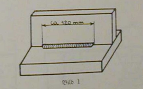 Figure 1
For the basic raw material one must choose ID mark P/P for armor material [or] ID mark P/B for [welding] armor material to St 52 KM [construction steel]. The thickness of the metal sheets shall not be below 20 mm for armor material and not less than 12 mm with St 52. Thickness of the fillet weld and number of application layers are optional. [They mean the right number of passes, chipping the slag off each time, for a given thickness of material. GL]
In each case, [the welds] are judged by:
a) the utility of the electrode regarding drop flow, slag flow, splattering, burn-in [annealing].
b) the appearance of the weld seam regarding annealing notches, smoothness of “caterpillar formation” [beading] [beading is fine, but I like caterpillars!GL], fissure formation,
c) the fracture’s appearance regarding pitting and/or cavities [pitting. GL . US standards had both pits and cavities – GE], flaking [slag formation], and combining failures.
The evaluation is based on the following criteria:
2 = good
3 = minor failures, but usable
4 = not satisfactory
The evaluations are to be recorded in a table in the written report. The basis for a complaint with scores of “3” and “4” are to be briefly noted.
Requested are: [Justification] for grades of 2 or 3 for each submitted evaluation. In case of an unsatisfactory evaluation, a repetition of a test can be made [and] in certain situations representatives of the manufacturer and the Naval High Command can be called upon to be present. Sufficient welding capability is the basic requirement for the usefulness of an electrode, and therefore, this is required without regard for other qualitative properties of strength: [but see strength testing criteria 7a &7b below]. [I think this means that if you can weld with it then that is more important than the other characteristics GL]
5. Crack Formation.
For testing crack [fissure] formation a fillet weld is drawn in the horizontal position as shown in Figure 1. Immediately, another somewhat thinner fillet weld is applied to the opposite side of the test [item]. After cooling, both seams are inspected with a magnifying glass for cracks.
As basic working material, ID P/P is chosen for armor plating, and St 52 KM [construction steel] for P/B. The thickness of the metal sheets for armor material shall not measure below 20 mm, for St 52 not below 12 mm. The fillet welds are to be drawn in only one direction. End-cavities must be exposed.
Requested are: fissure-free weld seams. Cavity [pitting] and fissures [cracks] need not lead to the condemnation of a delivery.
6. Welding of Butt Seams.
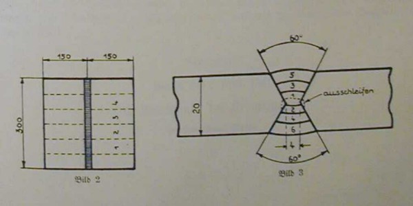
For the welding test of a butt-end seam, two sheets of metal, each [of which] is 20 mm thick, at least 300 mm long, and 150 wide, are to be worked at the longer edge, so that an X-shaped groove with and opening angle of 60 degrees occurs on both sides (Figures 2 and 3). In special cases, U-shaped grooves can also be prepared.
As basic material P/P as well as P/B electrodes can be used on Wh-raw material.
 Figures 2 and 3
[word on Figure 3 “ausschleifen” means “grind out or off” UR] [Translators Note: Robert Tougher, Tougher Industries, Albany, NY, does complicated welds, and this is his comment about these two figures:
“The diagram seems to show a root pass, a number of fillet passes and a cap pass on each side. They seem to be butt welding plate from the inside out, on both sides. Pipe welding is different, because you can only weld from the inside out in one direction. The root pass would be on the inside surface of the pipe and the cap pass on the outside. They're making 6 passes of weld of which they may grind a good percentage between each pass.”]
Welding is performed on both sides in a horizontal position. Before welding of the primary layer [commences], the tack-welded sheets are to be brought to body temperature [hand warmth/body temp is fine. GL/]. The primary layer should not be welded too lightly.
The routed groove on the reverse side should be cleaned out with a grinding wheel.
The number of layers is to be determined by the shop’s experience. The sequence is shown in Figure 3. During welding the metal sheets are not allowed to get warmer than is customary in the welding of large sheets. Therefore, resting pauses are to be instituted between the individual layers during test welding.
7. Testing of the Butt Seam.
a) X-ray test
An x-ray photograph is to be made after the metal sheets are welded. The test will be used for further investigations, if no accumulation of failure locations, no gross single failures, and no ruptures are detected. The results of the radiological examination may be used for the evaluation of the welding properties in regard to visualization of the fracture during horizontal welding.
b) Strength test
Four tensile strength test rods are to be machined from the welded plate[s] according to Figure 4 . The ridge bead is to be removed on both sides.
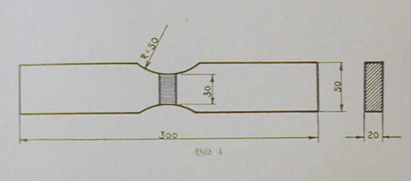 Figure 4 [self-explanatory. UR]
Requested is: The strength of at least 3 rods of the 4 tensile strength test rods must be at least 64 kg/square mm. If 2 or more of the 4 rods fail to reach the minimum value, the test can be repeated. If one of the four rods does not reach the minimum value of 64 kg/square mm, the supply lot is condemned unless the deficient value is clearly related to crater ruptures or faulty welding [procedure] and that there are no other complaints made.
Approved.
Berlin, 8 April 1941.
Naval Forces High Command
Deputy: Fuchs
Back to: Armour Information. | Bismarck & Tirpitz On-line Archive
|
