
BATTLESHIP BISMARCK ARTILLERY TESTING REPORT
Updated 02 October 2020
Control Number 45
Artillery Testing Command
for Ships [AVKS]
B.Nr. 700 Secret.Kiel, 31 May 1941.
Final report
AVKS Report No. 700/41 secret
AVKS Tests aboard Battleship ìBismarckî
Distribution.
| Office | ||
|
High Command of the Kriegsmarine [OKM] Inspection of Naval Artillery Fleet Command Commander of Cruisers Command of Battleship ìTirpitzî Testing Command for New Warship Construction [EKK] Ship Artillery School Artillery Testing Command ñ Land Naval Anti-aircraft and Coastal Artillery School Navy Shipyard, Kiel Navy Shipyard, Wilhelmshaven |
20 1 1 1 1 1 1 1 1 2 2 |
1-20 21 22 23 24 25 26 27 28 29-30 31-32 |
| In house: | ||
|
L R.I R.II T.I T.II A.I On Reserve |
1 1 1 1 1 1 2 |
33 34 35 36 37 38 39-40 |
I. Introductory remarks for the conduct of the tests.
-
A. 38 cm battery.
B. 15 cm battery.
C. Surface target fire control facility.
D. Telephone facilities of the surface target artillery.
E. Searchlight system.
F. Master [mother] gunnery aiming system.
G. Gyroscope rotation electric power supply.
H. Vo [muzzle velocity] measuring system.
III. Flak ñ artillery.
-
A. Flak deployment.
B. Flak fire control facility.
C. Flak telephone equipment.
D. Heavy Flak guns.
E. Light Flak guns.
F. Instructions and drawings.
IV. Rangefinder [Em] facility.
1. Tests in port.
The originally scheduled date for the AVKS time allotment for the battleship ìBismarckî was planned for the period from 3 February until 1 March 1941. This time frame could not be kept because the ship could not leave Hamburg until 6 March 1941 due to ice obstructions and closure of the Kaiser Wilhelm canal.
In order to take proper advantage of the enforced layover in Hamburg, the AVKS already boarded ìBismarckî on 29 January 1941.
In as far as the operational conditions and the circumstances allowed, tests were conducted during this time; in particular, investigations of the remote control for elevation of the heavy artillery (accuracy measurements, sluggishness [retardation, delay] and acceleration measurements of the hydraulics), the pre-ignition [fuse setting] mechanisms and Flak remote controls, the traversing directional devices of the Flak fire control stations, the drive controls of the rangefinder rotary domes, etc. Furthermore, the AVKS was substantially helpful to the shipís command for training (switching exercises, rapid transport exercises).
It has to be pointed out that important segments of the artillery installation would not have been ready for the AVKS tests, if the prolonged delay in port had not come to the rescue (e.g., elevation remote controls of the heavy artillery and Flak remote controls had not yet been accepted; the radar [Em-II] instrument had not yet been installed as well as some other items).
2. Tests at sea.
It was feasible to begin the tests at sea on 19 March 1941. At the start of the tests, a duration until 11 April was anticipated. Due to a new order from the High Command of the Kriegsmarine [OKM], which was sent only to the shipís command, the AVKS time, however, had to be cut short and to end on 2 April.
Under these complicating conditions, a considerable portion of the intended tests had to be abruptly dropped. More or less, only the conduct of those firing exercises remained intact that had immediate relevance for the training of the ship and the establishment of the physical readiness of the artillery installations. All tests that went beyond this, as those that primarily involved further technical development [fine tuning], such as shot-group [dispersion pattern] firing to determine the battery scatter as well as all measuring surveys of a technical nature, had to be regrettably stricken. The shot-group firing at anchor, to determine the battery scatter of the 38 cm battery have since then been obtained by a remedial make-up onboard ìTirpitzî.
For the conduct of the firing tests themselves, the following is noted:
-
a. Weather conditions.
As can be invariably expected in this season, the weather was extremely unfavorable for the conduct of the AVKS tests.
The constant lack of visibility was particularly disadvantageous.
Therefore, due to the combination of this, with the given lack of time, the stringent [AVKS] attention for measurement surveys was not enforced in the firing exercises.
Furthermore, especially the Flak shooting tests were not evaluated with the thoroughness that is mandatory and customary during AVKS firing.
Sea conditions that are sufficient for the shipís normal motions were not encountered in the firing range area, and, thus, the important [calibration] tests of stabilizing controls for spreads during more natural sea states could not be carried out.
b. Firing range area. Tests were conducted for sub-caliber firing in the western sector of the Bay of Danzig, with Gotenhafen as the target support depot, and for the full caliber firing off the base at Kahlberg, i.e., in the eastern sector of the Bay of Danzig, with Pillau as the target support base.
The steadily increasing interference with the artillery exercises in the Bay of Danzig due to the U-boat training areas, etc., is well known. The early availability of the base at Bornholm is, therefore, urgently requested. The establishment of this base by the Artillery Inspector [A.J.] is in progress. It is proposed that the naval shipyard at Kiel be ordered to immediately establish and equip a target support harbor on Bornholm in the vicinity of the base.
c. Target configuration. As the OKM is already aware, the towing and framing of target racks presented great difficulties; however, this was more or less satisfactorily resolved by the exertion of all participating stations.
The lack of mobilizing the target ship remote control squadron was a serious shortfall during the deployment and proper utilization of the caliber firing, namely, the 38 cm. In this context, it must be generally noted that our sled-mounted targets no longer suffice for the modern requirements of firing heavy caliber guns. Their mediocre speed and mobility does not allow for combat-like battle reality, which should always be employed during such firing. Their poor seaworthiness means that certain scheduled firing dates require frequent and intolerable restrictions. Their size has become inadequate to produce a usable target image at the great distances required for battle-charged firing. Lastly, they are much to easily damaged by hits and by nearby water columns, and their total or partial loss must be anticipated during each firing exercise.
In the future, only target ships will be considered adequate as an appropriate target display during firing of the new heavy caliber, and that will apply to practice charges as well as combat charges. Adequate amendments to the target ship regulations and the readiness of suitable target ship ammunition are mandatory.
For the rangefinding and position-fixing exercises, primarily done for the testing of the radar [Em-II] instrument, the Commander of Cruisers [B.d.K.] put at our disposal the cruiser ìEmdenî.
It was also noted that the He 111 aircraft, used for Flak target display, could only remain aloft for approximately 1 Ω hours; this is absolutely incomprehensible considering the purported action radius of this type of aircraft. In the future, these complications will require the readiness of two aircraft that can relieve each other during Flak firing tests of longer duration.
The available Stuka targets do not represent reality either, since they drop and dive much too slowly.
The firing on towed floating targets was not accomplished due to the lack of time and prevailing weather conditions.
Again, the urgent necessity for a radio connection between the airfield and the firing ship has been noted; although, this has not been accomplished by the present organization of the communications network.
3. General aspects.
-
a. Battery configuration.
The configuration of the 38 cm armament represents a well-laid out and thought out battery plan.
- Bracket group with normal partitioned salvoes ìforeí and ìaftî, thus, each salvo 4 shots.
- Bracket group with turret salvoes, with limiting [critical] salvoes (2 shots) by each turret and then a properly ìadjusted-for-positionî salvo with two turrets (4 shots) are fired, e.g., turret A/turret C + turret D/turret B.
The configuration of 2 twin turrets fore and aft, having sweep angles that have no dead zones or excessively large weak sectors, brings the requirements for tactical conduct, in terms of directional fire, down to the least complicated level.
In the future use of battleships it will be advantageous to have the capability of employing partial batteries when engaging in bow as well as stern combat actions.
The ship itself provides a stable platform for the battery. The effects of firing vibrations ñ even with full salvoes ñ remain within quite moderate and tolerable limits.
b. Turret construction. The construction of the 38 cm turret is appropriately functional. The advantages of twin turrets versus triple turrets in regard to clear overview, operation, ammunition transport, etc., are clearly apparent. There is sufficient space available in order to satisfy any aspect of military requirements for the visual survey of operational conditions among the individual platforms.
The actually occurring and objectionable individual deficiencies of turret equipment and design will be dealt with in the following itemized paragraphs.
c. Battery deployment.
-
α. During zeroing-in [Einschieþen].
For the normal zeroing-in with bracketing shot groups (rapid zeroing-in) two types of battery division are to be considered:
The partition salvoes in 2. have the advantage that a greater firing speed can be achieved within the bracketing group.
The firing tests showed that turret salvoes of 2 shots each, even at large battle distances, are sufficient for trial observations, and they give a generally acceptable appraisal of position due to the height and size of the 38 cm impacts. However, the partitioning does give 1. greater certainty in relation to observational capability, namely, in regard to turrets salvoes, since due to the failure of one barrel only one shot remains, and this is insufficient for judging position of lay.
Overall, for the firing of straddle groups, the example as described in the partition in 1., is, therefore, given preference. Further results are anticipated.
β. During firing for effect [Wirkungsschieþen]. For the normal battery deployment during fire-for-effect, obviously the appropriate manner is the firing of partitioned salvoes ìforeî and ìaftî (Turret A + B / Turret C + D). The firing of full salvoes does not present any difficulties for the batteries; however, this presents a drawback, first of all, because the opponent is harder to pin down due to the long interval between salvoes and because, the evaluation of the lay of 8 shots at the target can be considerably more difficult, since the size of the water columns of the shorter impacts can largely obscure the farther impacts. The firing of full salvoes during fire-for-effect is, therefore, to be used only in special situations.
A special report will follow.
4. Sight system.
-
a. Sight equipment.
The heavy turrets were equipped with only one dedicated sighting device during the testing period.
The sight was missing at the right aiming position, as well as all displays for the azimuth alignment of the turrets.
From statements by the [optical equipment production] firms and from their descriptions, one can surmise that a monocular sight is intended for the right aiming position. Furthermore, the description of the sighting equipment implies that the construction design of the sighting drive mechanism for the monocular sight, compared with the binocular sight, is considerably more complicated. The monocular sight will have tilt mirrors which will require a very delicate assembly of the sight drive mechanism. In considering effectiveness and operational reliability, the sighting device must be built as simple as is possible. Since the cant angle device [Krag = Kr‰ngungsabfeuerger‰t = cant/clinometer firing device or coincidence rangefinder] with its complicated assembly is no longer installed, the road for building simplified sighting devices is wide open. The reason for installing such a complicated drive mechanism for the monocular sight is not really apparent. It is urgently requested that the finalized equipment be installed as soon as possible and that it ought to consist of identical binocular telescopes for the left and right aiming stations.
b. Breakdown susceptibility of the sight drive. Since the sighting telescope is the last reserve for the alignment of the turret, it must be a fundamental requirement to assure absolute operational reliability. As an integral component of the gun it must be installed in such manner that it can always travel in tandem with its own barrel. Until now, for the present cross-ways alignment possibility of the right barrel from the left aiming station, i.e., the left barrel from the right aiming station, required long drive shafts to the right and left aiming station and intertwined sight connections. As a result, the entire turret sighting and direction indicating equipment becomes extremely vulnerable. This has, in fact, led to various failures. During the firing with direct alignment methods, two conical pins of the sighting connections were severed in two of the turrets, and this caused a misalignment of several degrees between the barrel and the sight. Furthermore, these discrepancies were not immediately noticed.
As an emergency measure, in agreement with the OKM, the sighting drives were accordingly modified, in a manner that disconnected the crossways interconnection. This requirement is categorically proposed for all ships which are equipped with the same sighting equipment as the battleship ìBismarckî.
Details of the simplification of the sighting drive mechanism can be obtained from the special report AVKS report No. 486 secret technical information of 12 January 1941 and the attached action pictures AVKS-drawing Nos. 1636 and 1637.
c. Shear connections [disengaging connection]. A fundamental error in the sight drive lies in the mounting of the shear connection. The shear connections, which simply serve as protection for the sighting drive as it goes to the dedicated sight instrument and only represents a single segment of the alignment process, are located immediately behind the drive for the elevation alignment rack [cog arc], i.e., in front of the junction to the mechanical indicator of the elevation angle receiver. This leads to a situation wherein the occurrence of a shear pin breakage, with the exception of elevation distance control, can cause the failure of all other alignment options. That means that practically all major alignment possibilities via backup are compromised, i.e., a questionable situation that must be avoided at all costs.
In so far as the proposed simplification for the sight mechanism in b. actually makes a shear coupling superfluous, it is further proposed that in new constructions the shear coupling be installed behind the branching that is located toward the elevation gauge receiver.
In the sighting mechanisms of the 38 cm turrets, there are presently shear pins with a diameter of 2.5 mm. According to data from representatives of the firms of Krupp and Rheinstahl, the sight mechanism drives for the 38 cm turrets are fundamentally the same as in the 15 cm turrets. Therefore, it is proposed that in regard to the simple matter of maintaining uniform spare part supplies and in order to avoid mix-ups, that the 38 cm turrets should also utilize 4.2 mm diameter shear pins just like those used in the 15 cm turrets.
d. Directional indicator [pointer] device The installation of the directional pointer device, in comparison with ships that were equipped with the cant [Krag = Kr‰ngungsabfeuerger‰t = clinometer or coincidence rangefinder firing device] devices, has not changed very much. After the removal of the secant device, the directional pointer device could have been designed in a more simplified fashion. In that way, a more convenient placement of the elevation value receiver would have been available. Presently, the elevation value receiver can only be viewed adequately by the aligner, when he is standing; it is otherwise impossible for him to make that observation because the light located on the mechanical directional pointer disk obstructs his view. Therefore, in order to provide better viewing conditions, the command [AVKS] has removed this illumination for the mechanical directional pointer, since that is only used as a backup anyway.
5. Main traversing machinery [mechanism].
-
a. Drive control characteristics.
The drive control characteristics of the traversing machinery are satisfactory.
They provide a steady traverse of the turrets.
The dead zone is very small.
Although a disadvantage was observed in that the mechanical transition delay [retardation] is very obvious between the low (potentiometer circuit switch) and higher speed increments. It does not differ from the effect of a stop at zero [full stop]. This does not give the aligner any clear indication if he has the control wheel in the zero position. The difference between the zero rest stop and the end stop of the potentiometer at the two laterally positioned transition stops must be clearly felt by the aligner.
b. Starter. The traversing machinery aboard the battleship ìBismarckî is the first of its kind to be started with a push-button starter by means of control relays [Steuersch¸tze = control relay, control contacts]. The starting sequence occurs in two steps. The oscillographically-determined current surges [pulses] of the two startup steps are very different. The current pulse of the circuit current consists of a first step of 623 Amps, and a second step of 1180 Amps. In order to prevent [damage from] excessive current surges in the shipís circuitry, it is deemed appropriate to select such startup steps that produce an even load on the network.
Basically, no military request has been made for this new type of starter switch because no substantial time-saving is derived for the mechanics personnel, and, in addition, the traversing machinery is only started up once at the beginning of the battle, making the advantages of the automatic startup negligible. On the other hand, the present-day startup automation fails to provide any possibility for a manual start of the traversing machinery.
c. Behavior of the traversing machinery during firing. In order to determine the circuit load produced by the traversing machinery and the behavior of the traversing machines themselves during firing with one barrel, oscillographic measurements [were] carried out. The results of these tests are presented in a special report (AVKS report No. 618 secret, 9 May 41). The analysis showed that the maximal current consumption from the network occurs while firing of a single barrel during the traversing [pivoting] adjustment. It amounts to 925 amps. An energy recovery [backflow] into the network does not occur. The oscillations that are produced by a shot dissipate in approximately 4.2 sec.
6. Elevation machinery.
In order to alleviate the load stress on the gear drives by the hydraulics, a cataract [hydraulic brake, dashpot] was built into the elevation aligning hand-wheel that is supposed to prevent the abrupt closing of the control sliders. This design severely impedes the alignment operations. Performance of alignment exercises has demonstrated that the upper limit for alignment of roll amounts to roll angles of about +/- 3 to 4 degrees. At 4 degrees angle of roll the alignment errors on average are about +/- 6/16 degrees, with outriders of up to +/- 10/16 degrees. At +/- 6 degrees angle of roll a realigning adjustment is impossible. In view of the alignment actions it would, therefore, be quite desirable to have a cataract that operates more smoothly.
On the other hand, it appears that the cataract does not fulfill its function anyway, since during hand alignment even harder knocks occur in the hydraulics than [would take place], for example, during elevation alignment done by remote control. It cannot be determined at present if these harder demands on the hydraulics could lead to damaging the hydraulics. At the start of the tests erosion wear was found on the tooth flanks of the elevation alignment rack and the elevation alignment pinion, and this was [found to be] the case in several turrets. Although these signs of erosion wear were noticed only in the loading position, it is suspected that there could be some other causes involved. (see also item 9.)
7. Alignment for elevation and azimuth.
The limits decrease also with increasing caliber, since the shipís motions during alignment for elevation and azimuth as well as the adjustment for the directional pointer, is dependent on the direct alignment procedure. [not sure of meaning here]. The maximal limit of the alignment [deviation?] of a 38 cm turret can be assumed to be about 4 degrees for the tilt angle for the elevation alignment device and about 3 degrees for the azimuth angle of the traversing mechanism. [not sure what that means].
It is not to be assumed that in the near future a noticeable progress can be expected by further improvement of the alignment systems per se.
This leads to the notion that even in the turret guns of the surface target artillery, the azimuth as well as the elevation alignment must be tested [calibrated]. According to experience with the Flak artillery, the expectation is that even here a simplified directional pointer is more suitable then the commonly used accelerated alignment. First of all, this applies to the constant compensating turns during yawing, i.e., while hobby-horsing [pitching]. Undoubtedly, the more compliant directional alignment will reduce the demands on the hydraulics and shipís electrical systems.
The on-board installed controls for azimuth and elevation could be improved with more simplified devices, e.g., with reversing differentials [?] for final alignment. A test is proposed to do just that.
8. Auxiliary elevation mechanism.
The required testing of the auxiliary elevation mechanism that was mandated by the testing procedure directive for the firing of actual shots could no longer be accomplished because of the curtailment of the testing period.
9. Characteristics of the hydraulic drive.
The calibration of the barrel elevation controls was difficult because the controls were very susceptible to oscillations. In order to determine the causes, detailed examinations of the hydraulic drive of the turrets were undertaken. The presumption was that the reason for the oscillation was the mechanical play [looseness] in the elevation drive, and that could be seen with bare eyes. In the investigations, both the static and the dynamic looseness were found. The following results were obtained:
-
a. Static errors:
The errors were determined with a cross-hair water-level quadrant [dragon-fly eye quadrant] and a stopwatch.
The looseness between the cog rod [rack] and the barrel measured:
-
1. At loading position: 1.5 mm, as measured from the cog rod [rack] at the drive cylinder, (that means 0.9/16 degrees at the barrel).
2. At 20 degrees barrel elevation: 1.2 mm, as measured at the cog rod [rack], (consists of 0.7/16 degree at the barrel).
Using a special testing device for the conduct of the oscillographic measurements of the static looseness between the cog rod and the receiver showed 1.9/16 degrees. During the measurements, a lateral deviation of the cog rod of 0.34 mm and a yielding by the drive cylinder in longitudinal direction by 0.55 mm was determined.
b. Dynamic errors: The oscillographically-determined dynamic play in the elevation alignment drive gave the following values:
-
1. Dynamic looseness between cog rod [rack] and cut-off signal:
Muzzle hoisting: 0.6/16 degrees }
Muzzle lowering: 1.1/16 degrees } Total looseness 1.7/16 degrees
2. Dynamic looseness between barrel and cut-off signal:
Muzzle hoisting: 0.2/16 degrees }
Muzzle lowering: 0.7/16 degrees } Total looseness 0.9/16 degrees
3. Dynamic looseness between cog rod [rack] and barrel:
Muzzle hoisting: 0.3/16 degrees }
Muzzle lowering: 0.5/16 degrees} Total looseness 0.8/16 degrees
c. Mechanical wear by the load on the transmission gear drives. As already noted in cipher 6, erosion wear had already occurred on the elevation rack as well as on the elevation pinion. Further tests must be conducted to determine if the cause of the erosion is related to the unsatisfactory adjustment [during assembly] or that it is due to the heavy load which occurs during manual aiming [alignment].
The firm expressed the suspicion that the gears had been insufficiently greased. Since at present there is no assurance that the rack and pinion will always be greased adequately, it is proposed that the rack is placed into a tub so that the rack and pinion is always operating submersed in lubricant (grease or viscous oil).
10. Performance rating of the electro-hydraulic remote control mechanisms.
During the layover in the harbor of Hamburg the opportunity arose to conduct a thorough investigation of the barrel elevation remote control. The investigations concerned themselves mainly with the determination of the relation [connection] between the hydraulic and electric systems and the elucidation of basic questions related to future improvements. The experimental results will be presented in a separate special report.
The following can be stated regarding the remote control:
-
a. Operational reliability.
No failures of the elevation remote controls occurred during caliber firing.
This, however, does not yet warrant a final judgment on the operational reliability, especially in reference to the experiences aboard ìPrinz Eugenî.
A final decision can be made when the elevation remote control has proven itself after a prolonged period of operation under the more demanding conditions that are part of the AVKS firing tests.
It must be pointed out that the elevation remote control was not released to the shipís command until shortly before the end of the testing period, despite the long layover in Hamburg; until then, personnel of the firm worked on it constantly.
b. Voltage dependency. It was observed that the elevation remote control is very sensitive to sudden voltage fluctuations. It does not matter how high the absolute voltage actually is, i.e., be it a constant 220 or 200 volts. The disadvantage is that a simple small voltage fluctuation of just a few volts has an effect that makes the control start to ìbreathî [puff, pulsate?] making the control error increasingly larger (see cipher 57). The cause for this voltage dependency is presumably the extra amplifier tube type SD 1A that is built into the network circuitry, i.e., the supplemental switch that it requires. Since voltage fluctuations are of such considerable extent in the turrets during operation of the pumps and the traversing machinery, the voltage dependency of the elevation remote control is particularly unfavorably affected. Corrective action is required.
c. Calibration [adjustment] characteristics. During the eight-week period that the AVKS was onboard, the calibrations of the elevation remote control had changed repeatedly, although the remote control had never been worked on. The reason for this [drift of calibration] could not be established with certainty. The drift in the calibration settings requires a continuous recalibration. Since the calibration work is very difficult and time-consuming, and since it cannot be readily performed by insufficiently trained mechanic personnel, this means that there will be a persistent uncertainty factor of this equipment for the time being.
d. Accuracy. Because of the lack of sufficient sea motion, the accuracy of the elevation remote control during sailing, the elevation control mechanism could only be determined with a sinusoidal oscilloscope. The oscillograms revealed a control error average misalignment of 7/16 degrees, but this also included several series of measurements of larger deviations of 9.5/16 degrees.
The control error of the elevation remote control was independent of whether the control sequence was just based on the elevation value indicator [Hw-Geber] ñ barrel alone, or the entire remote control chain of commands that was sent via alignment-elevation indicator [Rw-Hw-Geber], target indicator, alignment-elevation indicator [Rw-Hw-Geber] to the turret.
The number of larger errors, which occurred during several measurement series, can obviously be traced to very marked control-technical deficiencies, as for example, in the imprecise workings of both delayed-action increments [step-ups?] (more about this in the special report); moreover, the accuracy of the remote control of the 38 cm turret is completely inferior to the 28 cm and 20.3 cm turrets. In this, the substantially larger intrinsic dynamic forces of the 38 cm guns play a considerable role. A further reason is evident for this mechanical slack [looseness] is given in cipher 9.
11. Vo muzzle velocity settings for elevation by remote control.
The requirement for taking into account the Vo variation of the individual turrets during alignment of elevation by remote control has been repeatedly pointed out and it also applies to the 38 cm turrets. To accomplish this requirement, there are basically two alternatives:
-
a. Mechanical override by a parallel branch-off of the Vo correction to the Vo correction drive that leads to the elevation data receiver, and by overriding the mechanical differential between the trunnion bearings and the feedback device. [Meaning not understood. UR]
In order to reduce the use of long drive shafts, the elevation data feedback device should be mounted on the outer surface.
b. Electrical override by attachment of the Vo correction display to the Vo drum and a differential receiver spliced into the remote control cable bundle between the elevation data display and the elevation data feedback device. [Meaning not understood. UR]
-
a. Current-gate controls. The oscillographically-determined error in the current-gate controls of the azimuth-Vz [impact velocity] mechanism amounts to a 1/2 sixteenth degree.
The error runs smoothly.
The complete control circuit via target indicator, alignment-elevation indicator [Rw-Hw-Geber], all the way to the turret, consists of +/- 2 sixteenth degrees.
Due to the sequential switching of various controls, the effect of the fault [error] in the entire circuit [chain] is considerably more disruptive than it is when each of the controls is operated by itself.
A general deficiency is the unreliable functioning of the thermal connectors of the current-gate control; once it caused a nasty effect during one of the firings. This has been reported already in detail in AVKS report no. 524 secret TI [?] of 19 April 1941. It must be ensured that under all conditions, the current-gates do not fail for a duration of 3 minutes during the transition, when switching from stand-by to normal averaging operation [Havarie = average or disaster!]. The thermo-contact must provide adequate reliability during the duration of the switch-over procedure.
b. Labeling of control panel cabinets. At the present, the control boxes of the azimuth-Vz mechanisms are designated with a sign ìControl Cabinetî [ìSteuerschrankî] and a second sign ìArtillery remote control facilitiesî [ìArtl. Fernst. Anlagenî]. Both inscriptions on the signs make it clear that this designates the control cabinets for the azimuth-Vz mechanism. The second sign is to be changed to the following designation: ìAzimuth-Vz Mechanismî.
13. General items regarding the ammunition transport equipment.
The ammunition transport equipment could be tested only during rapid transport exercises in port and during firing in calm waters. A test while the ship was rolling was not possible [due to weather conditions]. A judgment as to the effectiveness of the ammunition transport equipment during swells [motion of the seas] cannot be submitted.
14. Main elevators.
The transport performance of the main elevators was determined with a stopwatch. It consisted of about 23 to 25 shots/minute [in total for all 4 turrets]. In addition to several failures of minor consequence, there occurred two elevator failures of fundamental relevance, and these require an in-depth retesting. The parking of the cartridge elevator in the cartridge loading station proceeds one-sided, i.e., the elevator has a support with a guide pin only on one side, while the other side is suspended freely in the elevator shaft. Disregarding the fact that this type of uneven load places stress conditions on the loaded elevator that are problems in themselves, but during operational failures, the one-sided support could lead, for example, due to particular external influences (trapping or seizure of a cartridge lid), to the inability of the elevator to park at the cartridge loading station and completely pass by and seat itself at the shell elevator at the shell loading station. This failure did occur aboard ìBismarckî and this led on each occasion to a complete and prolonged shut-down of the elevator. It is proposed that the construction design be changed in such a manner that the elevator is caught on both sides at the cartridge loading station. First of all, this would provide a better momentum distribution and it would especially achieve greater assurance for the flawless parking of the elevator.
15. By-pass of the hoist and transport winches.
The by-pass position of the hoist and transport winches of the shell chamber leads to serious failures because they did not open properly when the overhead trolley passed through, resulting in the crash of the trolley into the partially lifted stop [bed?].
The cause was the large amount of play in the by-pass drive.
Furthermore, the investigations revealed that the entire set of safety bolts in the adjustment connector [clutch?] had their nuts missing.
[The play in the drive] led to the loosening of the nuts and disconnection of the drive parts so that the by-passes no longer worked effectively.
Since the entire transport of ammunition depends on the flawless functioning of the hoist and transport winches, a great deal of emphasis must be placed on sturdy construction and reliable installation.
Details are separately pursued.
16. Reloader in the shell chambers [Granatkammern].
The redesign of the reloading [transfer] head in the shell chambers of ìBismarckî has prevented damage to the lifter [pestle, ram?] screw on the head of the shell during transfer. But if the ìRingwagenî [ring cart, carrousel, carriage?] has already been pivoted, before the reloader is backed away (which is certainly an operatorís error), then the lifting screw can still be damaged by the reloader [transfer] head. The guide on the head is attached in a way that, in its final position, is lateral to the lifting screw (i.e., at the carrousel). In order to prevent damage to the lifting screw, even in this case, the manufacturer ought to ascertain if there is a simple solution to correct this potential problem.
It seems appropriate to provide the reload transfer device with an additional second, reverse head for restacking projectiles in the rear storage area.
17. Turntables in the lateral cartridge chambers [Kartuschkammern]. Turret D.
For the transport of cartridges in the cartridge chambers, a turntable is provided for the upper chambers in turret D. The table is very space-robbing. The table is a real impediment for cartridge transport from the lower to the upper chamber. In order to improve the poor spatial arrangements that occur in the fully loaded cartridge chamber, the command [AVKS] has extended the planned cartridge pass-through table used for passing cartridges from the upper cartridge chamber to the carrousel cart far enough so that cartridges can be placed on it while still in the cartridge chamber. This measure has proven itself to be superior. The turntable is therefore superfluous and can be dismantled.
18. Capstan [windlass] machinery in the shell chambers [Geschoþkammern].
A windlass is available for transporting shells from the anterior shell stores of the chambers in turrets A and B. This arrangement is adequate. No operational difficulties arose.
19. Reloader [transfer loader].
The diameter of the transfer loader head is too small. During the pushing-out of cartridges from the elevator into the loading locker [cabinet] the lid of the main cartridges was dented because the contact surface of the transfer head is so small that the lid was dislodged. In order to avoid such problems, it is urgently recommended that the diameter of the transfer head be enlarged.
20. Blocking between the rammer and the loading conveyor.
At present, there is no blocking between the guide [rammer] and the loading conveyor [bail, crane]. Therefore, it is possible that an operator error could damage the guide with the loading conveyor. Although this blocking is desirable in the 38 cm turret, it is not considered absolutely vital. A blocking device seems only justified when it is necessary for operational safety and can be built without a major effort.
21. Shell casing ejection.
The drum ejector, with its shell casing ejector lid, which has been built into turret A, appears to be a considerable improvement over the customary ones in the other three heavy artillery turrets. Testing in heavy seas, however, was not possible. The present design, however, does not prevent the influx of water at the moment of casing ejection, because the drum has two diametrically-positioned locations on the drum that have cutouts for weight saving reasons. In order to achieve good water-tightness during casing ejection, it is proposed that the drum be provided with a housing that has a hinged cover on its front side for the insertion of the spent shell casings. The hinged covers should be attached in such a manner so that they can only be opened in the direction of the casing ejector and closed against seawater spray.
22. Shell casing receiving [catcher]device [H¸lsenfangvorrichtung].
The present construction of the shell casing receptacle is useless. The shell casing net is too small. During case ejection the casings often pop up so that they obstruct the catching device. The attachment was furthermore made in such a manner that the device did not freely transport the casings to the removal chute located at the barbette armor. Also, it happened repeatedly that this device, particularly at turret B, was bent by wind and water forces; and therefore, it had to be removed. A considerably stronger and more functional fabrication is necessary.
23. Auxiliary [accessory] elevators.
-
a. Receptacles [hampers].
The bottoms of the receptacles are poorly fastened.
The welding of the bottom and the attachment design are awkward.
During retrieval by the auxiliary elevator of empty cartridge casings from the gun platforms to the cartridge chambers, two receptacles lost their bottom during the loading of empty shells.
This matter is already under separate investigation.
b. Guide tracks. Special guide rails are mounted on the gun platform behind every barrel for ammunition transport with the auxiliary elevators. The mounting and dismounting of these rails is laborious and difficult because they are heavy and cumbersome. It is proposed to attach handles to the guide tracks, and, in addition, to select more functional means to facilitate their attachment in order to make mounting and dismounting quicker and easier.
24. Smoke evacuation.
The smoke evacuation in the turrets is still entirely unsatisfactory.
This evaluation is dependent on constantly different and changing environmental factors occurring in each individual turret, since the smoke conditions are heavily influenced by external factors (the shipís superstructures, turret orientation, wind direction, etc.).
Based on the few and comparatively brief firing exercises with full caliber ammunition during the brief AVKS testing period, a final judgment and more detailed proposals for improvement cannot yet be made.
The ship commands must report further observations.
N.E. [?] must attack the problem of designing and testing a fume-evacuating [blow-out] system in the barrel in order to obtain a radical solution to this problem.
As far as could be determined at present, a special fresh air supply duct for the machinery platform is considered unnecessary.
25. Smoke baffle lids.
The smoke baffles made by ìIsolaî, which were taken aboard for testing, were not proven useful. The testing has already been reported in AVKS Report No. 511 secret, of 16 April 1941.
26. Water-tightness of turrets.
At present, the barrel embrasure sealing gaskets are inadequate.
It was observed that during spraying with fire-extinguishing water, water does enter the turret.
This point was already followed up in OKM Report A Wa A Ib 4452 secret/41.
In the case of the cartridge shell ejector openings, see cipher 21.
The water-tightness of the bearing telescopes and their sealing gaskets against the turret armor plating was presently observed to be unsatisfactory.
Already at moderate seas, water seeps through the gaskets of the bearing telescopes into the turrets as well as into the bearing telescopes themselves, fogging them; this is particularly noticeable in the forward turrets.
Reference in this matter is made to the relevant reports from ships now deployed in the Atlantic.
Remedial action is urgently required.
A final evaluation of the barbette gaskets and the barrel gaskets cannot be made, since the there was insufficient wave action during the testing period.
27. Warning equipment.
-
a. Startup warning mechanism.
The startup warning mechanism [for the turrets] had not been completely installed by the end of the AVKS testing period.
Among other items, the danger zone safety switches were still missing.
b. Warning system for turrets firing at each other [Secondary artillery hitting heavy artillery].
The warning system to prevent firing interference was installed, but not operational, since the ball joints of the rack and pinion feedback mechanism were very loose.
Representatives of the Krupp Firm said that new ball joints are in the process of being manufactured.
The lack of this firing warning system represents a very serious danger when the batteries are deployed since there are no means available to prevent the danger of mutual accidental shooting at each other of the heavy and secondary artillery batteries.
28. Turret operations telecommunications loudspeaker system.
The noise levels in the 38 cm turret are considerably higher than in the 28 cm and 20.3 cm turrets. That pertains particularly to the machinery platform. Despite the fact that there are 3 loudspeakers with an output of 10 W each, this speaker volume does not penetrate to all locations of the machinery platform. Experiments with the a 4th loudspeaker, selectively positioned in various locations, showed that a substantial improvement could not be achieved, although echo effects were generated which distorted speech. In order to achieve an improvement, it is suggested that the now present directional loudspeakers in place, be replaced by mushroom-type omni-directional loudspeakers. An obviously better sound distribution will thereby be achieved that will more likely require speakers of lesser output.
29. Manual crank operation of the breech mechanism.
The manual crank handle of the breech mechanism should snap out of the way automatically as soon as the breech is closed so that it will not get hung up on the gun mount during elevation adjustment of the barrel. At present, the folding-away of the handle does not occur with absolute reliability. It repeatedly occurred that the cranking handle did not fold in the final end-position, and then broke off during elevation alignment. The cause apparently lies in the fact that the locking pin does not freely engage in the seating. A more functional design is necessary.
30. Azimuth drive of the bearing telescope.
The hand-wheels of the azimuth alignment of the bearing telescopes are at present located on the ceiling of the turrets. Since the bearing telescopes are often very sluggish in their lateral adjustment and can be moved laterally only by using a hand-wheel, it is proposed that a hand-wheel of similar design be attached right next to the bearing telescope, just as is the case with the artillery observation scope in the fire control stations.
31. Turret position indicator.
The degree increments are missing on the mechanical turret position indicators at the gun platform. Therefore, it cannot be determined in which lateral direction a particular turret is facing.
The attachment of electric turret position indicators, at present, is not very useful and logical. In order for the turret personnel to get an instant picture of its own turret position and that of the turret group itself, without rethinking, the turret position receivers are to be modified by turning them 90 degrees and adding an arrow, or some sort of mark, to the housing that indicates the shipís own axial position. The two receivers must then be logically mounted on the housing and calibrated to be truly analogous to the position of the turrets on the ship, i.e., to be observable side-by-side and fore and aft with the shipís longitudinal axis, and not as now, athwartships.
32. Availability of connections for dynamic tachometers and potentiometers.
As had already been requested in AVKS report no. 1455 T I of 1 August 1939, connections (flange couplings, etc.) for dynamic tachometers and potentiometers were to be provided in all new turret constructions [designs]. The availability of such connectors for testing instruments has proved to be useful in the systematic investigations of the traversing machinery and elevation adjustment machinery. The measuring instruments can then be connected at the testing locations as needed, without a great deal of preparation. This considerably speeds up turret inspections.
Since these installations were not available in the 38 cm turrets, and since the testing equipment that was originally built for AVKS tests by the ordnance technical group at the Wilhelmhaven proving grounds had been destroyed in an air raid, adequate measuring equipment could not be obtained due to time constraints.
The proposal is renewed that, in the future, the installation of receptacles for testing equipment within the turrets be accomplished during construction and that the required testing equipment is made ready in sufficient quantity.
33. Heating in the turrets.
The necessity concerning heating in the turrets has been previously reported in AVKS report no. 317 secret TI of 8 March 1941.
In regard to the dimensional volume of the heating capacity, it is concluded that the capacity of 50 kw in turret A is quite adequate, while the thermal capacity of only 13.5 kw in turret C is a considerable improvement, although it is not considered sufficient for all conditions.
Therefore, it is requested that all heavy turrets will be equipped with a heating capacity that is of the size of the one in turret A.
34. Ammunition transfer winches.
During the transfer of ammunition difficulties arose, since the Demag winches are installed separated from the elevator shafts. The signaling device for controlling the winches is inadequate. Insofar as the winches cannot be installed in the immediate proximity of the elevator shafts, it is in the interest of flawless operations to equip the winches with a remote handling [operating] control. Reference is made to Kriegsmarine Shipyard [Kriegsmarinewerft] Wilhelmshaven report no. secret 638 of 5 April 1941.
A simple proposal is to install a push-button switch that is attached to the Demag winch by a flexible electrical cable, which the operator, located near the elevator shaft, can hang around his neck.
35. Ammunition failures.
-
a. Fore cartridge [Vorkartusche].
During the firing of combat charges, severe charging [loading] errors occurred that were traced back to the preparation of the fore cartridges.
Because of the missing conical lid rings at the front end of the cartridges, they banged against the forward edge of barrel support device and broke apart, i.e., became lodged; and therefore, the firing with full combat charges had to be stopped.
The necessary modifications have already been done by special order.
b. Main cartridge [Hauptkartusche].
The mounting of the cartridge lid has again proven to be unsatisfactory.
Repeatedly, the lids came loose in the transport system and this led to obstructions due to wedging and transport failures.
In one incident, a loose lid wedged itself obliquely in the cartridge elevator shaft and subsequently dropped down all the way to the combat loading station, leading to the total failure of the entire elevator.
A drastic improvement of the lid fastening is required.
36. General aspects.
-
a. Battery layout.
The secondary artillery, with its 3 twin turrets on each side, represents a sufficiently strong, clearly arranged and practical torpedo boat defense battery.
In comparison with the ìGneisenauî weapons, the clean turret arrangement has gained considerably by its uniformity.
b. Turret construction.
Nothing of substance can be added to the ìGneisenauî report regarding the general turret layout.
The deviating construction of both aft mounts on both sides, where the turret only reaches down to the armored deck, provides considerable disadvantages, and should be avoided in future new construction if at all feasible.
The discontinuity in the ammunition transport route, the necessity of a special chain conveyor hoist leading from the ammunition chamber to the armored deck, and the interposition of a horizontal transport, assisted by special conveyors, makes this installation too complicated, and it consumes an unacceptable extra amount of manpower.
The spatial relationships on the gun platform have been improved in comparison with the initial conditions of the ìGneisenauî turrets by a more suitable mounting of instruments and other equipment, etc.
The rangefinder instruments of both middle turrets, which have not yet been installed, will undoubtedly reduce the overview of the gun platform severely and obscure, especially for the chief gunner, a clear view of both alignment stations.
c. Battery deployment.
The battery will fire at its best only with full salvoes.
During zeroing-in with bracketing groups, in order to save time, it is recommended to employ even battery partition during very favorable observational conditions; the most practical firing sequence is:
2 shots (turret I) - 4 shots (turret II + III) - 2 shots (turret I). However, the preferred method is to fire full salvoes, based on observational reliability.
The battery partition of left and right barrels is normally out of the question because of the disadvantage of the barrel interconnection.
d. Battery spread.
The intended shooting for determining battery spread could not be done because of the lack of time.
A change of the results that were obtained aboard ìGneisenauî, are not anticipated.
37. Sight equipment.
-
a. Equipment.
The 15 cm twin turrets were equipped during the testing period with one interdependent binocular sight on the left aiming station and with an interdependent monocular sight at the right aiming station.
The monocular sights are also insufficient in their optical performance as back-ups.
An early exchange of the monocular sights for binocular sights is, therefore, strongly advised.
b. Basic construction.
The construction of the sighting equipment is too complicated and, therefore, prone to failure.
Whatever was said about the design of the sights for the 38 cm turrets, under cipher 4, applies to the sights of the 15 cm turrets.
For more details, see AVKS report no. 486 secret TI of 12 April 1941.
c. Emergency disconnect [disengaging shear-pin connection]. During the full caliber firing with combat charges, a total of 7 shear connectors broke, because of the installed substandard shear pins. This breakdown led to the complete failure of the 15 cm turrets.
In retrospect, it was determined that disconnector shear pins of 3.5 mm diameter instead of 4.2 mm diameter were inserted.
Since the proper dimensions of the shear-pins were already established by the detailed AVKS tests on ìGneisenauî, and since it was resolved that shear-pins of 4.2 mm are required, it is incomprehensible why 3.5 mm shear-pins had been installed aboard ìBismarckî.
For further information see AVKS report no. 486 secret TI of 12 April 1941.
38. Alignment indicator for the manual operation of traversing mechanism.
The present design of the alignment indicator of the manual traverse mechanism, with which manual operation of the manual traverse mechanism is displayed and in which direction it is to be traversed [rotated], appears to be quite inadequate. The drive adjustment for the alignment mechanism is done with a hand-wheel located at the left, i.e., right aiming position, and its turns are transmitted to the alignment indicator via flexible shafts. The repeated severe kinking of these shafts led to jamming of the transfer mechanism and, therefore, to the failure of the alignment indicator.
It is proposed to replace the alignment indicator with the installation of a battery-free telephone. In order to do this, all that is needed for the lateral adjustment crew is to attach a microphone to the sight. Furthermore, a ìspyî [repeater] speaker needs to be placed at the machinery platform so that the crew of the manual traverse mechanism can overhear the orders that are given.
39. Elevation ñ velocity-at-target [Vz] [impact velocity] mechanism.
-
a. Current-gate control [Stromtorsteuerung].
The accuracy measurements of the current-gate control has been reported separately in AVKS report no. 594 secret TI of 19 April 1941.
The error of the current-gate control for the elevation-Vz mechanism itself amounts to +/- 1/2 to 1/16 degree, while the error in the complete control chain [circuit] of the components from aiming/elevation indicator to the target indicator in the turret is +/- 2/16 degrees. The effect of the control error, particularly in the complete control system, shows a pronounced random twisting motion with an amplitude of +/- 1/16 degree and a periodicity of 2 Ω seconds.
Concerning the insecure connections [fit] of the thermal contacts within the current-gate boxes, see cipher 12.
b. Identification of control panel boxes. The control boxes of the elevation-Vz [impact velocity] mechanisms are unsatisfactorily identified by their present identification labels. The wording "Control Cabinet" [ìSteuerschrankî] must be changed to "Control Cabinet ñ Elevation-Vz Mechanism" [ìSteuerschrank-Hˆhen-Vz Werkî].
40. Turret operations loudspeaker system.
The amplifier boxes on the gun platform for the turret operations loudspeaker system in the short turrets (II and III turret) are attached to the turret ceiling between the barrels. This mounting method is in dire need of change. During firing of the heavy Flak guns at low barrel elevation the amplifier tubes in the box blew up. The mounting must either be much better cushioned or the box must be mounted in a more protected location in the turret.
41. Ready-report lighted display panel.
The ready-report lighted display panels for the Chief Gunner are located at the left corner of the back-wall of the turret. In order to be able to observe them, the Chief Gunner must turn around. It is more functional, if the panel were mounted to the left of the firing switch box or obliquely on the turret ceiling immediately in front of the Chief Gunner.
42. Electrical turret position indicator.
Even the electrical turret position indicator is mounted disadvantageously for the gunnery chief.
It is located on the turretís left side at the level of the left lock [closure, breech].
After the mounting of the rangefinder in the middle turrets, it will no longer be seen from the gunnery chiefís position.
A transposition to the most advantageous proximity of the gunnery chiefís position is requested.
The requirement for receivers is, in a sense, the same as is listed in cipher 31.
43. Main elevators.
-
a. Piston rod fracture of the main control slide valve [switch].
In the main elevators of the short turrets [II and III turret], many cases of serious failures occurred during firing with exercise charges that led to the breakage of the main control slider-piston, and that forced a cease-fire.
The cause of the crash must first of all be seen as a result of the hard-entering of the elevator at the upper final rest stop. Since the failure occurred only with exercise ammunition and not with combat ammunition, it must be surmised that the weight limit for the entry speed was exceeded, because of the differential performance between practice ammunition and the combat ammunition. The failures did not occur in the long turrets since the surface area of the final stop approach switch can be set at the lower entrance speed of the elevators.
As a temporary measure, the mounting of compensating weights for the transport of ammunition was ordered. Furthermore, it is required that new adjustments be made in the short turrets for a slower entrance of the elevators at the upper ending position, as well as testing the materials used in the push rod.
Further matters have already been ordered by OKM A WaBA 9506 secret of 9 April 1941.
b. Reciprocal blocking of manual controls and automatic controls. The main elevatorsí control switch does not have a blocking device to prevent the inadvertent tripping of the ìautomatic operationî setting when the manual control lever of the elevator is in use. Thus, the inadvertent operation of the manual control lever may lead to major problems. For example, when the loaded elevator with a loaded platform is raised with the manual control lever, the elevator may briefly rise; and then it will be immediately returned to its original position at the loading position. The return will be a sudden stop induced by the main control slider and stop with a strong jerk which may produce damage to the elevator or a part of the controls, especially the hydraulics. The installation of a reliably working blocking mechanism is necessary for the exclusion of such operating problems.
c. Mounting of a lower control sliding switch. The lower control slider of the elevator control is at present placed on the outside of the elevator shaft without protection that allows for an unintentional activation of the slider. It is proposed that the slider be covered with an easily removable protective cover.
d. Stops for loading grooves [trays]. During the rapid incoming travel of shells or cartridges into the elevator, it occurs frequently that shells or cartridges remain in the loading trays because of flip-overs in the grooves. It seems advisable that loading trays be equipped with a stop and counterweight so that they can be tilted only to the extent that ammunitions are secure from flipping over in the elevators.
44. Ammunitions transport installation outside the turret.
-
a. The ratchets [latches] present in the chain hoists for the pick-up of cartridges and shells are attached with aluminum rivets.
This method of fastening is totally inadequate. The latches broke off repeatedly.
b. The guide troughs for the chain hoists leading to the turrets are encased in wood. This type of encasement is not durable enough. The wood will become rough and will splinter, and that will increase the friction produced by the shells and cartridges very considerably. It is proposed that the troughs be encased with light weight metal or equipped with rollers.
45. Shell ejection.
The design of the shell ejector on the turretís floor appears awkward. In order to prevent surging seawater entering the turret from below, more functional shell ejection shoots should be attached to the backside of the turret.
46. Fume exhaust.
The evacuation of fumes is not sufficient. During extended periods of firing it is only possible to operate the turret by opening the turret portholes [for ventilation], and especially from the residual after-burn of flare ammunition that generates a large amount of fume accumulation on the gun platform.
47. Heating in the turrets.
Even for the 15 cm turrets, heating is absolutely necessary. See AVKS report no. 317 secret of 8 March 1941.
48. Warning systems.
The proposed warning system planned for turrets I and III for preventing firing ìagainst each otherî - one half year after commissioning ñ is still not operationally ready. The warning devices are still missing. In addition, a few installation jobs of cable re-routings, i.e., the switchboard system, had not yet been accomplished by the shipyard. Since the warning system for prevention of ìself inflicted attackî by the secondary artillery is of particular importance, such a work delay is intolerable for any reason whatsoever.
49. Access to connections for testing equipment.
Even in the 15 cm turrets it is desirable to have built-in devices installed during construction for the necessary measuring instruments used in conducting measurement tests of the traversing and elevation machinery. Compare with cipher 32 in regard to the 38 cm turrets.
50. Layout and construction of the artillery command posts [Artillerieleitst‰nde].
-
a. Foretop, forward station and aft station.
The layout and construction of the command posts is functionally designed.
The spatial requirements are sufficient.
In comparison with ìScharnhorstî and ìGneisenauî, averaging [Havarie] switchboard boxes are added to the forward artillery fire control station. But the view and the operations are not impaired by this.
In the final AVKS report for the battleship ìGneisenauî and the cruiser ìPrinz Eugenî, it was already requested that the order transmitters, firing signal indicator, opponent assigner, and salvo sequence [pace] clock be removed from the artillery command posts.
This removal is also anew and urgently requested for the instruments are still present aboard ìBismarckî, excepting the retention of the ready-fire report lights present in the fire signal indicator [Feuersignalgeber]. It should be replaced by smaller ready-to-fire reporting light displays.
In addition, the removal, i.e., prohibition of installations in new command post constructions, of the rangefinder receiver is requested. They are really meaningless in the command posts since the rangefinder receiver only selectively provides the distance [computations] of the night rangefinders (focsíl instruments and Flak fire control instruments), and the night rangefinders are generally not used during daytime sea battles anyway due to their short range.
b. Night command posts. (Applies only to ìBismarckî. The setup aboard ìTirpitzî for the night command posts and the equipment mountings is different.)
The layout of the night command post of the battleship ìBismarckî can be considered a success in comparison with the night command posts of the battleships ìScharnhorstî and ìGneisenauî.
The absence of the box-shaped design provides for considerably better overview and accessibility.
The forward section of the night control station is, however, obstructed by the command post.
The area of the command post must have sufficient space so that the shipís command and the artillery coordinator have sufficiently free overviews of both sides and ready access from one side to the other.
This requirement has not yet been fully met aboard ìBismarckî.
The present configuration of the flare shells launching control equipment [Lg-Leitger‰tes] is totally nonfunctional and unsatisfactory.
More about that in cipher 54.
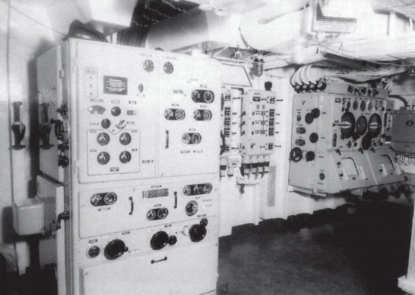
51. Arrangement of the operations switchboard and computer stations.
The room size in the artillery computer stations [Rechenstellen] is quite adequate. Operational conflicts do not even arise when the computer station is fully staffed. At any time, the command transmitter officer [BÐ-Offizier] can obtain a sufficient overview over the activity of the individual crew members.
The artillery switchboard stations [Schaltstellen] are also provided with ample space. The switching panelsí design are clearly arranged. Therefore, the engineering personal has the opportunity to rapidly accomplish the ordered switching, and to obtain a clear overview of their present switch settings.
Artillery computer station (Artillerie Rechenstelle).
52. Artillery gunnery data computer [Schuþwertrechner].
Nothing substantially noteworthy to report.
In the interest of design simplification of individual computer components, it must be reiterated that it has been proven once again that they are superfluous aboard the battleship ìBismarckî.
This concerns, in particular, the entire equipment arrangement for setting command transmission switches and the equipment for manually setting sight angles at the gunnery data computer itself.
It seems important that in the future the opponentís data, which are displayed on the photoelectric board [screen], are instantly transmitted from the gunnery computer to the photoelectric board. It has been demonstrated again that the settings on the gunnery computer display of the opponent indicator are very unsatisfactory. This produces an awkward effect on the firing evaluation.
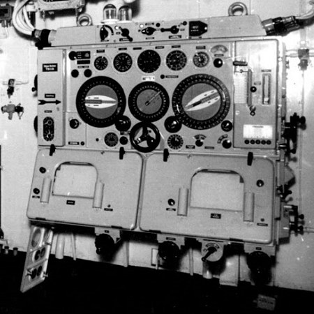
Gunnery data computer (Schuþwertrechner).
53. Firing signal indicator [Feuersignalgeber].
-
a. Switching device for partial salvoes.
The switching for partial salvoes within the fire signal indicator for the heavy artillery and secondary artillery is provided in the following sequence:
-
Partial salvo I: left barrel.
Partial salvo II: right barrel.
This arrangement does not conform to the normal battery partition.
Two years ago, it was already pointed out that such settings of the normal partition of fire must be modified, namely, in the forward and aft battery groups.
(AVKS report number 550 secret, of 5 May 1939).
Here, the partition of salvoes must be as follows:
-
Heavy artillery:
Partial salvo I: turret A - turret B
Partial salvo II: turret C - turret D
Secondary Artillery:
Partial salvo I: I turret
Partial salvo II: II + III turret
The ship commands have already taken their own appropriate action for changes on their fire signal command indicators.
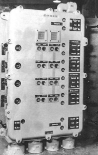
Fire Signal Indicator (Feuersignalgeber).
b. Differential acknowledgment receiver on the firing signal indicator in the computer station.
Proceedings: OKM A Wa A IIb report n. 2401/41 secret of 24 March 1941.
The question regarding the necessity of the differential acknowledgment receiver in the firing signal indicator of the computer station was again thoroughly inspected and tested by the AVKS aboard ìBismarck".
The results obtained have substantiated anew the necessity of this monitoring receiver.
The monitoring receiver is an excellent and indispensable tool with which the command transmitter officer [BÐ-Offizier] can gain, at any time, an overview of the actual alignment status of the battery. The ability to follow the aligning movements puts him into a position to coordinate the operations of the fire control command with the actual activities of the battery. Furthermore, in this manner, a considerable augmentation of firing rapidity is achieved.
The advantage of the monitor does not just lead to an immediate increase in the rapidity of fire, but especially, in the ability to readily discern abnormalities and to correct them immediately. Delay errors in firing can be immediately recognized and immediately transmitted to the commander. Even errors by the fire control system or in the alignment equipment can be recognized without delay and shut down, i.e., effectively dealt with.
The following examples based on practical experience are given:
-
1. During a battle by the cruiser ìAdmiral Hipperî, the fracture of a connector pin in the pointing [aiming] instrument in Turret C lead to gross range dispersions.
This failure was first observed on the computer stationís firing signal indicator monitoring receiver.
2. During the full caliber tests by the AVKS of the heavy artillery aboard ìBismarckî, a misalignment of two turrets occurred while using direct alignment methods; this failure was due to the fracture of a cone-shaped pin in the sight connector of the sight gear drive. The operating personnel of the turrets did not immediately recognize this failure. Had there been a monitoring indicator for the proper barrel position in the computer station, the problem would have been immediately recognized.
There is an additional load placed by the 10 degree acknowledgment receiver on the elevation indicator within the alignment-elevation indicator, but a possible degradation of performance in the dynamic accuracy of the firing data converter from about º to Ω /16th degree is negligible when compared with the advantages of the acknowledgment receiver, and this can be tolerated.
The recent advance of having an alignment teletype in the turrets does not represent a replacement of the acknowledgment receiver in the fire signal indicators. A continuous monitoring of firing can only be achieved by having a centralized station.
The weight of the cable required for moving of the acknowledgment receiver from the turrets to the computer stations is of no consequence, particularly when one considers the savings contributed by the removal of other equipment which was proposed a long time ago, but has not yet been carried out. (Compare to cipher 50).
The AVKS takes the position that a case is at hand here that provides sufficient justification based on the additional material requirements of the facility and its military importance.
54. The star shell guide unit [Lg-Leitger‰t].
-
a. Placement of the unit.
The placement of this unit, as was previously mentioned, is extremely awkward.
Perhaps this is because it is considered temporary.
The star shell guide unit must be relocated to the computing station below decks, as has already been requested previously.
In referring to the final report of ìPrinz Eugenî, it is again proposed to house the star shell computer, as well as the star shell indicator, in the [central] computer station.
b. Construction of the unit.
Likewise, the final report of ìPrinz Eugenî is referred to in regard to the construction of the unit.
The request stated there, regarding the removal of the star shell guide unitís turning knob, is herewith repeated.
Aboard ìBismarckî, dysfunction of the unit was caused by the turning of the knob shortly before star shell firing commenced; the operating crew did not realize what consequences this can have.
55. Control circuits of the surface target fire control center.
-
a. Aiming device [target acquisition].
The contingency measure in the forward and aft stations of switching the target aiming posts [Ziels‰ulen] from one side to the other side is superfluous and can be omitted.
Furthermore, it is deemed nonessential that the target indicators [Zielgeber] in the foretop are given target designations from the aiming posts [Ziels‰ulen] of the forward station, since, during night battles, the heavy artillery is basically directed by the forward, i.e., aft command posts.
As a temporary measure for the present switchboard circuitry, it is proposed that the targeting indicator axles of the individual target indicators make use of the freed-up switch settings for the radar [EM-II] units, as follows:
-
1. The central target indicator [Zielgeber C/38] of the foretop will receive, in place of the target acquisition from the aiming posts [Ziels‰ulen C/38] of the forward station, the target acquisition from the azimuth bearing instruments [seitenpeilger‰ten] of the forward station and the foretop.
2. The lateral target indicators [Zielgeber C/38] in the foretop will receive, in place of the target acquisition from the aiming posts [Ziels‰ulen C/38] of the forward station, the target acquisition from the azimuth bearing instruments [seitenpeilger‰ten] of the foretop and the aft station.
3. The central target indicator [Zielgeber C/38] of the forward station will retain without change the target acquisition of both aiming posts [Ziels‰ulen C/38] of the forward station.
4. The lateral target indicators [Zielgeber C/38] of the forward station will receive, in place of the target acquisition from the aiming posts [Ziels‰ulen C/38] of the other side, the target acquisition from the azimuth bearing instruments [seitenpeilger‰ten] of the forward station and the target indicator of the aft station according to the azimuth bearing instruments of the aft station.
As a final solution, the possibility needs to be anticipated that each target indicator can readily select any lateral bearing unit from the target indicator of the forward and aft station to supplement the target acquisition on their side.
b. Identification signs for simultaneously activated settings. The identification signs attached to the switchboard boxes have proven satisfactory for indicating the simultaneously activated settings of individual switching axles. It is deemed appropriate that the wording [meaning] of these signs should also be inscribed on the switchboard operating procedure sheets.
56. Average settings for the surface target fire control center.
In comparison with the original design of the average settings aboard the battleships ìScharnhorstî and ìGneisenauî, the switch settings on ìBismarckî have been designed so that in addition to the overall average settings, a partitioned average setting can be made for the stations, i.e., the guns, for the heavy artillery as well as for the secondary artillery.
No difficulties related to switching occurred during the use of average settings. It can be accomplished quite rapidly.
57. Current-gate controls [Stromtorsteuerung].
-
a. Thermal contacts for the current-gate controls.
The failure of the azimuth-impact velocity unit due to the breakdown of thermal contacts was reported in cipher 12.
This particular failure in the azimuth-impact velocity unit categorically applies to all current-gate controls.
b. Additional amplifier tubes of the type SD 1A in the current-grid circuit. The investigations conducted on the current-gate controls revealed that the controls are extremely sensitive to current fluctuations and especially to sudden fluctuations. The magnitude of the changes itself has no effect. Of significance is simply the rapidity with which the current changes.
The high susceptibility to current changes is very likely related to the additionally installed amplifier tubes SD 1A [triode made by Telefunken] into the current grid, that were, in the first place, added to the sensitive switching control. As far as it is known from the manufactureís personnel involved in the tests, the amplifier tube was installed only to correct errors after it was shown that there was an insufficiency during maximum demand.
Since current fluctuations in the shipís circuit can always be assumed to occur, this pre-amplification, can, under certain conditions, markedly impede the quality of the current-gate controls, although ìthe characteristics setting of the controlsî may not initially require it. The results of the tests will be presented in a special report. (AVKS report no. 718, secret/41).
58. Speaking buttons on the head-set telephone equipment.
The presently available telephone equipment has certain problems in that the wrong operation of the speaking lever can considerably disrupt fire control by producing additional noise interference. Very often, the telephone gear that is connected, but not in use, has the microphone lever in a constantly open position because of how it was hung on the wall. Since the microphone lever of the present design does not always prevent this, it is proposed that the microphone lever be replaced by a push-button. The attachment of the push-button should be made in such a way as to make its unintentional activation impossible.
59. Radar [Em-II] telephone.
The ìEm-II-telephoneî, with its special rerouting work and telephone outlets, is superfluous. At all locations where telephone outlets for this telephone have been placed, there are connections for the ìEm-telephoneî. The demands of the Em-II-telephone can certainly be assumed by the regular rangefinder [Em] telephone.
60. Telephone units without batteries.
The battery-less telephone units that proved themselves as a last resort communication already aboard ìGneisenauî have been permanently installed on ìBismarckî as single wall-mounted units. The units have proved themselves because of their low functional delay and their simple operation. A further development of these telecommunication units for future new constructions is recommended.
61. Switchboard rerouting of the gunnery telephone system.
The simultaneous switching of the gunnery telephone facility has been changed according to a proposal by the AVKS (AVKS final report battleship ìGneisenauî) so that the switching of the gunnery telephone no longer depends on the fire signal axis (Fs-axis), but rather the target indicator axis (heavy artillery, i.e., secondary artillery). The change is still missing on the labels on the switch-boxes regarding the co-activated settings.
62. Splinter protection cowls for searchlights.
The present splinter cowls on searchlights 2 and 3 do not have their own power-assisted aids for opening and closing. The movement of the splinter cowls is presently very cumbersome and requires a great deal of time. It is proposed that fleet command take the position that further observations be made on the necessity of a power-assisted operating device.
63. Average switch settings for the searchlight facility.
The fire control settings related to the searchlight average settings are partitioned in such a manner that the primary guidance values transmitted to the searchlight director device [Scheinwerferrichtger‰t] are separated from the primary data provided by the aiming device of the searchlightís own [local] alignment mechanism. The transmission switch-over of the guidance values to the searchlight director device is made separately by verification conducted via the searchlight buttons in the remote control box. Since the searchlight and the searchlight director device are a single unit, it is deemed more logical and simpler to combine the entire searchlight installation in such a manner that the average settings of the unit can be conducted with a common button, i.e., the present searchlight button that is presently on the remote control box.
64. Layout of the master aiming facility.
The master aiming facility is arranged functionally.
The available space is quite ample.
The subdivision of the rooms into one component room and one special switchboard room is convenient.
The overview of the facility is thereby considerably improved and the maintenance is simplified.
65. The output of the gyroscopic power supply is, as is the present case aboard ìPrinz Eugenî, quite sufficient.
The available power reserves, as well as those of the forward and aft gyroscopic power supplies, are more than 100% [of the required power].
The interconnections of the facility within the ship are logical.
66. Cathode-ray tube oscillograph.
Since the Vo measuring system had only been partially completed, no final judgment can be rendered.
As far as the brief testing period allows, it can be said that the quadruple cathode graph recorder, which is the first of its kind ever to be installed, proved effective from a purely technical and operational perspective.
A deficiency has surfaced anew that the quadruple cathode graph instrument, just as had been in use in the former single cathode tube scopes aboard the battleship ìGneisenauî, has no selectively adjustable locking device for the reversible moving part that allows several rapid salvoes to be photographed on single film [plate].
The system could only be tested during the firing of the secondary artillery. The measurement results obtained are attached in the special report of the AVKS ñ caliber firing ìBismarckî.
67. Connection for the Vo measuring system to the central firing device.
The connection of the Vo measuring system to the central firing device was originally designed so that the actuating impulse for the deployment of the cathode graph scope and for the initiation of the timing device in the turret would be connected by ìS clampsî. Consequently, the entire additional electrical load of the Vo measuring system (14 relays, approx. 6 amps) had to be absorbed by the central firing device. Since the central firing device, however, is only fused for 2 amps, the fuses burned out when the initial operating sequence of the Vo measuring system was begun during the firing start-up. This led to serious disruptions during firing. In order to continue Vo measuring, the connection with the central firing device was done via attachments on the ìD clampsî, i.e., in back of the firing relays. Since the turretís electric firing circuit is considerably more heavily fused than the central firing circuit, no more failures occurred due to the connection of the Vo measuring system.
68. Drilling access ports into the barrels [for data collection probes].
Now, since the cathode graph scope has become a permanently installed onboard system, it is incomprehensible why, at the same time, the barrels were not drilled to accept the measuring probes.
If there is any hesitation about permitting the drilling of the barrels, then the cathode graph scopes, which have now been even provided with their own rooms, are simply carried aboard ship as dead ballast.
Aboard ìBismarckî, only the 15 cm barrels had been drilled for the planned shot group [strike picture] firing; while the 38 cm barrels had not been drilled at all. Presently, the same applies to ìTirpitzî, so that, unfortunately, no shot group [strike pictures] of the heavy artillery could be made by the AVKS, despite both completely installed cathode graph systems, and thus, no Vo, nor sequential total measurements, could be carried out at all.
69. Configuration of the Flak battle stations [Flakeinsatzst‰nde].
-
a. Main Flak battle station [Hauptflakeinsatzstand].
The problem with the Flak battle stations cannot yet be considered as resolved.
Similar to the ìGneisenauî ships and the heavy cruisers, the present design of the main flak battle stations by virtue of their very limited area of view, do not measure up to their requirements.
Since the Flak combat director does not have a simultaneous overview to all sides, two Flak combat directors must be on hand during battle, in order that one can deploy the weapons of the portside, while the other deploys the weapons of the starboard side.
Furthermore, due to the numerous order transmitters [B.Ð.'s] and the small amount of space allocation in the foretop galleryís battle station, there is an excessive accumulation of people who are not protected by any kind of splinter shielding.
According to the battle roster, the following personnel were present on the main Flak battle station of ìBismarckî:
2 Flak combat directors.
1 master sergeant as order transmitter supervisor.
8 Flak deployment order transmitters.
4 target alignment crew.
1 weapon deployment order transmitter for the shipís command.
1 order transmitter for Flak command telephone.
1 ordnance mate as record keeper.
1 signalman for E.S. [Erkennungssignal?] delivery.
1 officer as torpedo-danger observer.
2-4 ensigns as torpedo-danger observers.
A total of 23 -25 men
It is quite evident how such a conglomeration of people in tight quarters must interfere with Flak deployment.
In the final report of the cruiser ìPrinz Eugenî, it was already proposed that the deployment director is to be provided with an appropriately constructed space in the rotary dome on the foretop.
Furthermore, the proposal clearly suggests that, in the interest of improving the transmittal of commands and space considerations, a special ìFlak deployment centralî be established.
The following organization of the Flak deployment appears to be more logical:
-
1. Flak battle station [Flakeinsatzstand] in the rotary dome of the foretop.
Here, there will be 1 order transmitter [B.Ð.] for interconnection with the shipís command and the artillery command and 1 order transmitter for connection with the deployment central.
2 Target designation devices [Zielanweiseger‰t] (2 gunnery aligners) in the foretop gallery.
2. Flak battle central [Flakeinsatzzentrale].
The present location is under the armored deck in close proximity to the Flak computation stations [Flakrechenstellen].
In case remodeling of the ìBismarckî class ships is possible, they should be housed in the present air communications central.
This is the location for the rest of the order transmitters.
These are under the supervision of a non-commissioned officer who serves as order transmitting officer-in-charge [B.Ð.-Offizier] of the required telephone connections and switchboard panels.
(1 order transmitter for the reply telephone,
4 order transmitters for heavy Flak deployment,
4 order transmitters for light Flak deployment,
1 order transmitter for the wall telephones).
3. Connections.
Communication between the battle leader and the battle central is important for transmitting the orders of the battle leader via a loudspeaker system (one for each microphone on the main Flak battle station as well as the forward and aft reserve Flak battle station).
In the central deployment facility, there must be equipment for the transfer of orders from the order transmitter via the director-, gunnery-, and rangefinder telephones to the individual Flak groups.
For responding reports from the battle central to the Flak battle station, there must be a special acknowledgment telephone that can act simultaneously as the command line from the battle station to the battle central and be used in case of a failure in the loudspeaker system.
The command transmitting officer [B.Ð.-Offizier] in the battle central is connected with the acknowledgment telephone via his headphone; the battle leader can listen into the headset of the battle station order transmitterís acknowledgment telephone.
The lay-out of a Flak battle central facility has, first of all, the following advantages:
-
1. The battle order transmitters are assembled in a closed compartment below deck and are shielded against splinter effects.
The order transmission to the Flak groups is not disrupted by influences of weather, apparent wind, or battle noise.
2. The number of order transmitters as well as the accompanying telephones and switchboard boxes equipment can be greatly reduced.
3. During failure of the main Flak battle station due to the effects of hits, the battle order transmitters, as well as the order transmitter systems, of the Flak battle central remain clear. The Flak deployment can be taken over in a very short time by the reserve Flak battle stations by switching the loudspeaker system of the battle central to the microphone of the forward or aft reserve Flak battle station and by the simultaneous connection of the acknowledgment telephone.
Certain disadvantages are perceived in the proposed arrangement in comparison with the present one, since the simultaneously arriving sighting reports of the various Flak groups can be reported only via one telephone line (acknowledgment telephone) and that the Zags [target designation devices] are unavailable for immediate action for the battle leader because of their positional separation.
It is proposed that advice on this matter be obtained from the fleet command and the Artillery Inspector [A.J.].
b. Reserve [back-up] Flak battle stations [Reserve-Flakeinsatzst‰nde].
-
1. The forward reserve Flak station is virtually unusable in its present configuration.
After the E.K.K. [Erprobungskommando f¸r Kriegsschiffneubauten] testing time, the telephone connectors for Flak deployment were removed from the forward night command post.
This was because during night combat missions the night command post has such an accumulation of personnel (shipís command, searchlight alignment devices, target columns, order transmitters for the shipís command and artillery command) that there is no room left for the Flak deployment personnel.
The telephone connections were relocated to the aft edge of the forward night command post.
From this location, the view ahead through the night command post, aft and above through the mast and superstructures, and through the forward Flak command posts, is totally obscured.
2. Even the aft reserve Flak deployment station is of only limited usefulness. The space allotment is extremely tight. There is only room on the platform for one deployment commander and, at best, 2 order transmitters. The other order transmitters must find space below the deployment station on the aft signal station. Therefore, the platform must be widened. The sweep angle of the station is sufficient. However, the installation of the ball-mounted Flak director stations will somewhat restrict the aft view.
It would be logical to substantially elevate the aft deployment station.
The bulwark of the station is not high enough. The Flak deployment commander and look-out are severely affected by the apparent wind, and raising the bulwark is required.
In regard to equipping the reserve Flak deployment station with telephone connections and bearing instruments, see cipher 72 and 88.
70. Layout of the target designation device [Zag = Zielanweiseger‰t].
Equipping the entire Flak deployment with only two Zag units is inadequate. During attacks from various directions a rapid deployment is only possible if there is a Zag for each heavy Flak group. A selective changeover of the Zag to individual stations using the telecommunication box of the main Flak deployment station is not feasible during radial-concentric attacks and rapidly appearing targets, especially because the switch box is only present on one side.
For the finalized Zag equipment configuration, four Zags are to be requisitioned. Each Flak group must be permanently assigned one Zag.
It is proposed that 2 Zags be installed at the main Flak battle station [in the foretop gallery] and 2 Zags at the aft reserve Flak battle station. The normal settings for the Zag: forward Zag for the forward group, aft Zag for the aft group. Since the Zag alignment number is connected via the command telephone of a particular group to the main Flak command post, there is no difficulty in issuing orders and target designation for the aft Zag.
Advantages of this arrangement:
-
1. During failures of the main Flak deployment station, only two Zags are lost simultaneously.
2. The aft reserve Flak station is also equipped with fully capable Zag.
3. There are fewer instruments in the main Flak deployment station, hence better overview.
71. Construction of the Zag.
The construction of the Zag has already been dealt with in detail in the final report of the cruiser ìPrinz Eugenî. Overall, the Zag has also been proven a useful equipment aboard ìBismarckî. The following deficiencies are again pointed out:
-
a. The instrument is, overall, bulky and space-consuming.
b. Based on the target commands from the Flak deployment commander, the aligner does not have an opportunity to search for the target and read off from the instrument indicator scale the target values for elevation and azimuth. It is requested that the indicator scales be moved to the front of the instrument, and slanted upward in such a manner that they can be read off by the aligner. It would be desirable to design an azimuth disc and an elevation scale that is right in the optics.
c. Equally difficult is aiming the Zag with the aid of the sighting device attached to the instrument. It is proposed that the auxiliary sight be installed right above the telescopeís ocular.
72. Bearing [azimuth] discs [compass] instrument with auxiliary sight.
The azimuth discs with auxiliary sights that are installed in the main Flak command station have proven themselves as very useful target designation instruments in the hands of the Flak commander. They are simple in construction and operation. It is proposed that each reserve Flak deployment station be equipped with 2 such bearing discs.
73. Layout of the Flak command stations [Flakleitst‰nde].
The question arises as to whether the two Flak command stations put onboard would have been better positioned at the starboard and port sides of the [fore]mast or amidships aft. This cannot be solved decisively and has become outdated anyway. The advantages and disadvantages of both arrangements in regard to the sweep angle and susceptibility to hits are both important considerations.
74. Construction of the Flak command stations.
As an addendum to the final report of the Cruiser ìPrinz Eugenî, it must be added that the basic remodeling proposals concerning the construction of the spherical Flak command stations, type SL 8, have proven effective anew aboard the battleship ìBismarckî; the local separation of the rotary ring compartment and the mechanical operations compartment of the Flak command stations A and B are not efficient. In case of failures, the mechanical personnel are required to climb out of their normal battle stations (rotary compartment) and enter the operations compartment by a detour in order to get at the remote control equipment of the operations compartment. In order to perform maintenance and repairs, a direct entrance way from the rotary compartment to the mechanical operations compartment is required.
75. Operational reliability of the Flak command stations.
The operational reliability of the remote-controlled Flak command stations in contrast to the directly stabilized Flak command stations has undoubtedly become better. However, during the brief time of the AVKS tests at sea, failures occurred repeatedly, that resulted, in part, in total shut-down of the Flak command stations. However, this concerns failures that in principle have nothing to do with stabilization.
The causes that led to major failures can be found below:
-
a. Variable excitation of the coarse and fine adjustment systems of the tilt and edge angle remote controls.
The tilts and edge angle remote controls consist of fine adjustment systems (10 degrees) that are operated at 333 Hz, 80 to 120 V, and the systems are actuated when the gyros are turned up and the switch for the tilt and edge angle remote control are turned on.
The coarse systems (180 degrees) are operated at 50 Hz, and 55 V, and are activated in tandem with the fire control system, i.e., only when a calculator device [Reg] is switched on by the Flak command, which is indicated by the warning light in the main switchboard panel.
In this way, the stabilization synchronization becomes dependent on the fire control switchboard, and, in the final analysis, on the 50 Hz alternating current circuit.
It happened in several instances that the command stationís Flak remote control was put into operation without activating the fire control switchboard; this lead to a false stabilization, i.e., if the stabilization output was positioned in the final setting.
For removing the dependency between the stabilization and fire command, it is required that the presently installed coarse adjustment be replaced by the 333 Hz systems on all Flak command stations of ships that are equipped with type SL 8 Flak command station. These can be replaced during dockyard layovers in order to make the switchboard of the Flak command stationís remote control independent of the fire command switch.
b. Defective mounting and manufacture of the drive assembly parts. A further defect of a very serious nature, which caused a 2 day shut-down in Flak command station B, came about because the driveshaft broke for the propulsion pinion of the alignment indicator. The fractured surface of the drive demonstrated typical signs of stress fatigue. Furthermore, there was considerable wear on all teeth of the flank face of a ring gear and on the addendum teeth. Places of wear were also present on the spline drives of the alignment indicator, the alignment control motors, and the oscillation compensator adjuster.
The cause which led to the fracture could be related to the fact that the alignment indicatorís cog driveshaft was severely recessed and a notching occurred. On the other hand, the alignment indicatorís cog drive was too tightly fitted to the ring gear so that the shaft was taxed by bending stresses. According to the firmís personnel, tests of the gyro instruments showed that the ring gear was off-center by about 0.7 mm, and, additionally, a cog surface of the ring gear was poorly cut.
Since the station was not fully pegged-down before firing was begun, although the insertion of the pegs was only done later, it is also possible that a displacement of the entire station from the base structure occurred due to shell shock during firing.
c. Illogical construction of housings for the remote control switch cabinets. The covers of the remote control cabinets are stiffened internally with cross-ways welded sheet metal. It occurred that contact was made between several soldering spots of equalizing aligners with cover stiffeners, and that that led to short-outs. The Flak command station therefore went into the end [final] position. Therefore, a more functional design of the cabinets is required.
d. Oscillation of the drive motor for the power unit amplifier. Oscillations occurred in the drive motor of the tilt angle amplifier transformer of Flak command station B. The oscillations presented themselves in a form that of greatly variable rotational speed, and the current demand rose in rhythm with the oscillations, as high as 120 amps. The normal current of the drive motor consists of 7 amps. Therefore, considerable circuit loads arose which led to severe current drops in the Flak command stations. Since the rotational number variations of the drive motor affected the tilt angle itself, the matter was investigated further. This showed that the brushes of the drive motor were completely erroneously adjusted. After resetting the brushes, the oscillations no longer occurred.
76. Stabilization of the Flak command stations.
-
a. Horizontal stabilization [Horizontstabilisierung].
A thorough investigation of the horizontal stabilization could not be made due to the lack of time and sufficient seaway.
Whether and to what extent the installation of the turning gyros led to an improvement, can, therefore, not be judged.
A partial investigation of the elevation stabilization the roll dampers [sensors] also could not be made, since the opportunity did not arise for mounting the permanently installed gyros on top of the roll damper.
It was demonstrated once again that remote controls, i.e., remote control systems for onboard operation, must be installed in such a manner that they can also be tested on a calm ship in harbor waters. Since it is well-known that the remote gyro control can only be tested in a heeling ship, i.e., with a rolling damper [sensor?] on which the gyros are mounted, their utility for onboard operation is severely limited unless suitable testing equipment is also installed with the introduction of the remote controls.
This request is even more urgent, since the lay-up in shipyard, etc., meant that the remote gyro control could not be calibrated in the harbor and cannot, therefore, be turned over to the shipís command. It is now always required that the shipyard personnel travel on board and wait until the ship starts to roll in order to be able to make final remote control adjustments. Since the rolling movement of the ìBismarckî was quite low, the fine adjustment of the gyros by the firmís certified personnel could finally be accomplished, after waiting for weeks, at the end of the testing period.
During special experiments on the tilt angle remote control it was discovered that activated remote controls had already [been put] in the rest position, i.e., without change of the tilt angle value, via an alternating current of 10 Hertz frequency circulating in the control circuit. This alternating current is not influenced by the error [default?] current. The control motor produces oscillation cycles that equal the detected frequency. The cause of these fluctuations may be related to throttle amplifier feedback connections (one within the first operations circuit and the second in the damping motor circuit), since the feedback connections [connectors] are easily susceptible to self-induced oscillations if they are too strong. The oscillations within the remote control could lead to an overload, i.e., overheating of the remote control innards, and cause the tilt and edge angle drive mechanisms to wear out. A detailed report about these experiments is presented separately. (AVKS report no. 723 secret/1941).
b. Azimuth [lateral] stabilization [Seitenstabilisierung].
New viewpoints regarding the azimuth stabilization cannot be presented.
The continuation of the tests conducted on ìPrinz Eugenî involving the accuracy controls of the azimuth stabilization using a longitudinal baseline survey could similarly not be carried out due to lack of time.
77. Switchboard of the tilt and edge angle remote controls.
The direct current feed for the Flak command stations aboard the battleship ìBismarckî, in contrast to the cruiser ìPrinz Eugenî, no longer comes from the switchboards of the gyro current control room, but directly from the shipís circuit. The automatic switchover is located in the rotary compartment.
The feed for the remote controls and the gyro is dependent on the setting of the operating switch in the gyro current room. At the ìstart-upî and ìoperationî setting, the gyro, as well as the main switch box for the rotary current bus bar, from where the feed for the remote controls and the support motor controls are tapped, are operated on a three phase current. The former setting ìreverse operationî ñ which involved a breaking of the gyro, is no longer required ñ the harbor operation setting is now used. At this setting, the gyros are no longer powered; and thus the bus board in the main switchbox is only connected to two phase outputs; since the alignment value remote control operates on two phase. However, three phases are required for the operations of the tilt and edge angle remote controls and the support motor controls.
Hence, the contingency does not exist that would allow operating the remote controls without also operating the gyros. However, this contingency must be made available. During shipyard completion, various facilities must often be made operationally ready at different times, and it is necessary to test completed facilities without interfering with work on other facilities.
The possibility of separating the gyro and remote controls is imperative for fine tuning the remote controls for accurate symmetry; and this can only be done when certain components are ëlashed downí, i.e., with stopped gyros.
An asymmetric calibration of the remote controls creates a constant error. It occurs because the asymmetryís specific fault current voltage is counterbalanced. During an interruption of the fault current (e.g., burn-out of the fuse in the bridging circuit), the remote control becomes single-sided. Therefore, each time the fault current was lacking, the instrument of Station A aboard the battleship ìBismarckî returned to the tilt angle final [stop] position. A correct recalibration of the remote control was not possible due to the impossibility of activating the remote control while the gyros were immobile.
Therefore, it must be requested that the rotary current bus board of the main switchbox be provided with three-phase current in order to facilitate the separation of the gyro and remote control units.
Since the gyros used in the ADE [?] component are displacement current flow devices, a step-up of the gyros with a step-up transformer is no longer required. Therefore, it becomes unnecessary to activate the operation switch from the rotary current location. It is proposed that in future new constructions, the operation switch be relocated from the gyro rotary current compartment to the rotary ring compartment, and to incorporate it in parallel into the feed switches present in the main switch box. The advantage of this layout is that all switching procedures are concentrated in the hands of the command post mechanic, thus, providing a more rapid operational readiness of the post.
A schematic outline of the proposed switching change is proposed separately.
78. Harbor [shore] power supply switchboard with remote control.
As was first noted onboard, there exists a difference between the harbor operation switchboard of the Flak command stations of the cruiser ìPrinz Eugenî and the battleship ìBismarckî. Now the Flak command stations can go into action in port when the gyros are shut-down and while the alignment remote control is still functioning. It is now possible to align the guns with the alignment data unit while the gyros are down since the port switchboard can be directly linked to the Flak command station and no longer needs a target alignment that involves the gyro.
79. Reciprocal interference between Rw [Richtwinkel] alignment angle and Sv [Seitenvorhalt] lateral lead remote controls.
In order to determine quantitatively the reciprocal interference of the Rw and Sv remote controls, the investigations, initiated aboard the cruiser ìPrinz Eugenî and continued aboard the battleship ìBismarckî, required some testing equipment that had to be installed to obtain the desired results.
The testing results again indicated that the interference on the Rw remote control system by the Sv remote control is considerable. The lateral deviations of the range finder platform from the target position were derived from photographs of practice firing, depending on the given velocity with which the Sv value is changed, in amounts to +/- 1 degree. Since the rangefinder has at total field of vision of only 1.5 degrees, when the rangefinder has been set at 40x magnification, the target is completely pushed out of the rangefinderís field of vision by the oscillations of the two remote controls. The deviations occur at very sporadic intervals making a lateral realignment impossible and the rangefinder is, therefore, considerably impaired in its effectiveness.
A separate report will deal in detail with the testing results and proposals for changes.
80. Azimuth alignment devices of the Flak command posts.
Of the present four aiming possibilities:
-
a. path alignment
b. speed alignment (normal gear mode)
c. speed alignment (high gear mode)
d. manual alignment
... the path guidance is recommended for use, when possible, because of its well-known operational advantages.
The speed guidance control, whose two speed levels are accessed via an intermediate gear shaft, at a ratio of 1:4, is burdened with considerable operational difficulties. The rapid stop of the high speed operating mode, from maximum to zero, requires 7 full manual wheel cranks and 28 in the normal gear mode. Since the transition from ìchange targetî to ìpursue targetî most often involves an abrupt change of speed (for target change high, for target pursuit lower speed), the reverse turns of the hand-wheel always consumes considerable time and also causes great difficulties for target acquisition.
The same difficulties arise during the transition from speed alignment to path alignment. In this procedure, the speed control must first be turned down to zero, otherwise the stationís lateral bearing is always off at one side.
The difficulties are even more pronounced since the speed control drive (Heinau-drives) has no tactile zero position. There is small, barely visible pointer attached to the control steering column. In order to recognize the zero setting, the lateral aligning man has to turn away from the optics and interrupt the target observation. This can lead to the loss of the target due to the alignment telescopesí poor field of vision. The path alignment in the present configuration, however, does not permit achieving the necessary alignment speed for target acquisition. This has already been described in the AVKS final report of cruiser ìPrinz Eugenî.
The further follow-up and appropriate modifications according to the final report of ìPrinz Eugenî are encouraged. This involves the addition to the present path alignment control of two speed levels of approximate ratios of 1:4 and 1:5. The shifting for the choice of the two speed levels is activated most effectively by a foot pedal and in such a manner that the high gear, i.e., the high gear ratio, is activated by depression. When the foot pedal is released, the normal gear setting will be automatically activated by the force of a spring.
The path speed gear shaft can then be deleted, whereby the source of the error is also deleted.
81. Periscopic-leveling telescope C/9.
The inaccessibility of the periscopic-leveling telescope C/9 in the Flak command posts has already been reported in the final report ìPrinz Eugenî. The present auxiliary sights have proven themselves to be sufficient for the target designation by the Flak commander.
82. Design of the Flak computer and switching stations.
The space of the Flak computer stations [Flak-Rechenstellen] is quite sufficient.
Since there are only four Flak command stations and since the calculators [Regs = Rechenger‰t] are permanently assigned to the Flak command stations, final equipping with 4 Regs (2 Regs for each computer station) is considered sufficient.
The preliminary equipment of only 2 Regs, one for the forward and one for the aft computer stations appears to be effective.
The layout of the switching cabinets in the Flak switching stations [Flak-Schalstellen] is concise and the operation is greatly facilitated.
83. Computer/calculator Reg C/VI.
Nothing new in regard to Reg C/VI.
During the performance of the tests on the Flak elevation remote control, a second 10 degree elevation value differential pick-up [?] was found (gyro system) that was nowhere described in the available switchboard settings.
It is mechanically and electrically connected to the remote control tack of the 10 degree Siemens differential pick-up system that is installed in the Reg.
According to the gyro instruments [Kreiselger‰te] firmís representative, the system is provided with enough adaptability to be updated, for example, when the Flak elevation remote controls, which are now Siemens controls, are later replaced by controls from the Firma Kreiselger‰te.
Since it is assumed that the Siemens controls will remain onboard because their entire equipment has been properly installed, it is proposed to remove the superfluous and unnecessary displays [Geber = pick-ups?].
84. Steam influx into the forward regulator machinery compartment.
In order to prevent steam influx, none of the steam pipelines may be routed through the weapons operation compartments. However, aboard ìBismarckî, there are steam pipelines routed right through the anteroom of the forward regulator machinery compartment in which the circulating cooling system for the regulator machinery is housed. During one night, a flange of this steam pipeline became leaky without being immediately noticed, and thus, steam forced its way through the airshaft of the circulating cooling system that leads from the access room to the forward regulator machine room. This resulted in a total loss of the entire current gate controls of the forward regulator machinery compartment for the duration of several days. After the clean-up and drying-out of the control cabinets, almost all remote controls had to be recalibrated and that required a long time.
It must be guaranteed that no steam pipes are laid into the access rooms that are connected to the weapon compartments via ventilation, cooling etc.
85. Designation changes of the regulator machinery compartments.
The compartments which at this time house the amplifier equipment for the Flak and rangefinder remote controls, are designated: ìRegulator Machinery Compartmentî.
This designation is not appropriate. The main purpose of these compartments is the housing of the amplifier cabinets (current gate amplifiers). The still present GV [?]-aggregates [transformers], which are also considered amplifier equipment, are presently in separate adjacent rooms.
It is proposed that, for the entire compartment, analogous to the surface target artillery, be given the following chosen designation: ìForward, i.e., Aft Flak-Amplifier Compartmentî.
In this compartment, all amplifier equipment for the Flak is to be housed in a convenient manner, that is, also those that are still in the Flak computer station (elevation transfer) and in the Flak switching station (targeting control, lateral lead control).
86. Basic layout of the Flak telephone system.
The basic layout and allocation of the individual Flak telephone facilities for the individual battle-stations and their intended use overall, does not reflect military needs in many cases.
It has been repeatedly observed aboard ships that Flak telephone facilities, in particular the automatic systems, are used for entirely different purposes than for what they were originally intended. For example, aboard the battleship ìBismarckî, the Flak command telephone equipment is used as the Flak deployment telephone unit, since the weapons deployment telephone system is completely occupied by the surface target artillery system. Consequently, the weapons traffic telephone system is still being used as the Flak command telephone system. Since the distribution was done according to a plan for the stations based on the originally intended purposes of the individual installations, the present distribution of the connectors only partially meets military demands.
Often, the present remedy was to accommodate the wishes of the individual commands as far as possible. Therefore, the installations aboard individual ships are no longer uniform.
The basic structure of the modern Flak telephone system relates back to the prior proposal (The Flak Primer manual) that was previously made in AVKS report no. 200 secret, RI of 20 February 1935. Since conditions have changed considerably in the interim, and new insights have been obtained from war experiences, the re-evaluation of this important question is definitely required.
The AVKS must refrain from taking a comprehensive position because it does not have a Flak expert with sufficient onboard experience at its disposal. Nevertheless, it is proposed to submit the entire bulk of questions to a panel of experts with frontline experience and of professional authorities so that they can conduct a new comprehensive analysis.
87. Expansion of the weapons telephone-traffic facility [Waffenverkehrsfernsprechanlage].
It has become necessary to provide a connection at the foretop gallery for the weapons telephone traffic system. At this time, it is impossible for the Flak deployment commander and the technical personnel present on the foretop gallery to communicate instantly with the weapons operation rooms in case of a malfunction report.
Furthermore, it is deemed necessary to install an auxiliary connection for the weapons telephone traffic system in the operational compartments of the Flak stations A and B. The present telephone connection of the Flak command posts is now in the rotary ring compartment. Since both compartments are spatially separated, there is at present no manner of communication between them.
88. Telephone jacks for the aft reserve Flak battle station.
Since the aft reserve Flak command station is separated physically from the aft night command post, the telephone connections that are present there cannot be used. Therefore, an additional connection in the aft reserve Flak deployment station must be made to connect the weapons deployment with the shipís command, artillery command, and for the weapons telephone traffic to the weapons operation rooms.
89. Signal facility for Flak deployment.
The humming sound system proposed in the final report of ìPrinz Eugenî that would superimpose humming sounds on the Flak command telephone at ìCease, battery ceaseî i.e., at ìChange, target changeî was put aboard the battleship ìBismarckî as an experimental device for the AVKS tests. During the conduct of the Flak firing tests this system basically proved itself. However, the humming sound must be increased in intensity so that it can be more easily differentiated from voice sounds.
90. Battery layout.
The layout of the battery into 4 groups of 2 x 10.5 cm twin Flak mounts each is advantageous and is overall proper for the demands of combat.
The Flak protective screen facing forward is relatively weak.
The spatial accommodations at the guns are, in part, quite tight, especially in the abeam firing direction.
The completed enlargement of the platforms of the 4 aft Flak positions (twin mount C/37) has proved itself as being necessary.
The fitting-out with two different types of mounts (twin mount C/31 and C/37), due to special conditions, has considerable operational disadvantages.
For more information, see cipher 92. and 93.
An early compliance to arms uniformity is urgently requested.
91. Assembly of the 10.5 cm rapid loading gun C/33 in the 10.5 cm twin mount C/37.
The twin mount C/37 offers more space within the protective shield in contrast with the C/31.
The operation and overview of the gun is therefore improved.
The design of the sequential indicator systems is more clearly visible.
The newly constructed sights (suspended alignment disc [circle]) achieved a simplification in the aiming system. It provides larger viewing apertures for the alignment crew. The capture of the target during direct aiming is facilitated considerably in comparison with the C/31 twin mount. The flip-in of the auxiliary sight from the outside by a special operator is no longer required.
By contrast, the large sighting notches have a disadvantage in that the sensitive parts of the gunís fire command facility and the alignment machinery are exposed to heavier amounts of boarding sea spray and that the aligners, namely during direct alignment, are severely impaired in their work by the apparent wind.
The sight design with a moveable ocular requires that the alignment crew must constantly alter their body position during changes in elevation angle. The oculars move a distance of 21 cm during the raising of the barrel from the lower to the upper extreme position. Since the seats do not have springs, the aligner has to compensate for this large movement with his body contortions. It must be requested that the pivot of the sight optics viewer be relocated to the level of the neck of the aligner.
92. Missing lateral lead converter.
On the twin mount C/37, the slider hand-wheel on the gun moves the aiming telescope in the suspended aiming circle according to the dialed-in slider value that is indicated on the slider receiver. Since no lateral lead converter is present, the computed value for the horizontal plane obtained from the Reg calculator is erroneously entered as the slider value in the slant range plane in the sighting device.
This indicates that it is presently impossible to fire by ìslider indicatorî at aerial targets when switching the twin mount C/37 from the Reg and Flak command stations. This means that after failure of the alignment angle and elevation angle, these guns can only be fired by direct aiming methods according to the ìcorrection indicator and slider via the telephoneî. Remediation by the installation of a lateral lead converter on the guns for the recalculation of the horizontal slider into the slant slider is urgently necessary.
This matter has already been further investigated in AVKS report no. 185 secret TI of 13 February 1941.
93. Sight end-position switching [Visierendlagenschalter] of the 10.5 cm twin mount C/37.
As has already been reported in AVKS report no. 191 secret TI of 28 February 41, very serious deficiencies were found in the sight end-position of the switches of the 10.5 cm twin mount C/37 that severely restrict the elevation range of the guns during remote control operation.
The sight end-position switches are set with such great reliability (large switch handle) that they deactivate the elevation remote control over a wide range of settings. The following data for the switch settings on the gun were determined: A setting of 0 degrees in the lower sight end-position represents actually - 4 degrees. After activation of the lower sight end-position switch, a movement of the barrels by the remote control systems (i.e., at fully automatic, at semi-automatic and manual mechanical control) was only possible in the upward position, since the downward mobility is being blocked. In order to put the end-position switch back into the ìnumber oneî position, and to achieve a remote control operation into both directions, the barrels must first of all be raised up to a considerable elevation angle. This angle amounted to 28 degrees. This indicates that at the setting of an angle correction of say 15 degrees, the lower sight end-position switch is already at +11 degrees and the barrel must first be raised to more than 39 degrees in order for the gun to be under remote control operation and so that it can again work in both directions of movement. Since the upper sight end-position switches have similar problems, the elevation range is even more impaired, although the remote control operation in both directions is unaffected.
Based on the faulty conditions described, firing at sea targets or firing against low-flying aircraft with the 10.5 cm S.K. C/33 in the C/37 twin mount is practically impossible by direct aiming of the guns with the available mechanical elevation alignment devices.
Measures of amelioration have already been issued by the OKM A Wa [ordnance section] B d 4442/41 of 25 March 1941. The contemplated modifications could not be tested, since they had not been conducted before the end of the AVKS testing time.
94. Edge angle drive [Kantwinkelantrieb] of the 10.5 cm rapid-loading gun C/33 in the 10.5 cm twin mount C/37.
Repeated failures of the edge angle drive of the twin mount C/37, led to complete jams of the guns in the edge angle axle. [ìKantwinkelî or edge angle is the angle that is parallel with the gunís ìbeddingî on the ship and is perpendicular to the elevation angle].
The initiated investigations led to the following results:
The edge-angle alignment mechanism of the twin Flak in the C/37 mount is, in contrast with the twin Flak in the mount C/31, mounted in such a way that in the manual alignment drive there is a worm-gear (for absorption of the recoil); while in the remote control drive, there is a direct transmittance of the edge-angle via cog drives. The transition from manual operation to remote control operation, and in reverse, is done by an operator throwing a recoil-spring coupling lever. However, this does not activate the final connection itself. The activation of the coupling lever causes only the tensioning of the spring in the coupling drive. Only the force of the spring causes an on or off engagement of the coupling device, and only then, when coupling jaws are in the proper position. In order to perform the coupling operation properly, the hand-wheel must first be moved back and forth so that the coupling can properly engage before throwing the recoil spring lever for tensioning of the spring.
The coupling equipment consists of a total of 2 different couplings, of which one is in the drive train for manual alignment and the other is seated in the remote control drive train. The coupling positions overlap so much that, for example, during the transition from manual alignment to remote control operation, the coupling in the remote control drive is already engaged when the coupling for the manual operation is not yet disengaged.
The remote control motor is equipped with a spring brake which has the purpose of effectively braking the control motor and thus the entire edge-angle mechanism in case of a current loss in the remote control drive. The brake also ìspeaksî when the safety switch is open, i.e., when shifting from manual to remote operation is not yet completely done.
In the event that the coupling rods are very stiff, the possibility exists that the coupling is only engaged up to the overlap, and then the spring does not have the power to complete the shifting. Thus, both drives are engaged, and since the motor brake is fully engaged as long as the safety switch is open, both drives are blocking each other.
On the other hand, if the safety switch is not calibrated so that closes only after the coupling is securely engaged in the drive train for manual alignment, and when the operating switch is engaged before shifting, then the remote control motor works in reverse against the worm-gear and freezes it up so completely that it cannot be moved by hand nor by remote control. The reactivation of the edge-angle alignment drive is only possible after the motor brake has been loosened.
In order to prevent further problems with the gun, first of all, the magnetic brake of the control motors and the spring in the coupling rods was removed. No further problems occurred after the removal of the brakes.
Further remedial measures have been decreed in the meantime with OKM A Wa Ba 6401 secret of 21 March 1941.
95. Performance rating of the Flak elevation remote control [Flak-Hˆhenfernsteuerung].
In a continuation of testing the Flak elevation remote control, which had been started aboard the cruiser ìPrinz Eugenî, oscillographic measurements were made. Since tests could not be conducted in a rolling ship due to a lack of sea motion, the tests were limited by using an artificial rolling motion device [???].
The actual results indicate that aboard ìBismarckî the performance rating of the elevation remote control alone is better than the score that was given at the time of the cruiser ìPrinz Eugenî tests, based on the entire remote control errors. The average error band [tracing?] of the remote control consists of about 25/16 degrees when the sine transmitter is set at the maximal speed of 8 degrees per second. No adverse influences were detected during the power system control for target elevation. It can, therefore, be concluded that the noisy process of stabilization that occurred aboard the cruiser ìPrinz Eugenísî Flak gun, (see AVKS special report, report no. 1260 secret TIII of 20 December 1940), can be traced back to the inadequate control characteristics of the controls for tilt and edge angle in the Flak command post itself.
The precise test results that were recorded in oscillograms will be presented in a special report AVKS report n. 721 secret/41.
96. Performance rating of the Flak edge angle remote control [Flak-Kantwinkelfernsteuerung].
Tests with the sine scope showed that the error of the Flak edge angle remote control amounts to an average of +/- 1/16 degree at a maximal speed of 6 degrees/second.
In regard to the progression of the error and the influence on the edge angle remote control by the preset remote control at the Flak command station, basically, the same problem is present as was described for the Flak elevation remote control (see #95 above).
The final results will be presented in a special report AVKS report no. 722 secret/41.
97. Examination of the behavior of the edge angle mechanical movement [Kantrichtwerkes] of the 10.5 cm twin mount C/37 during a unilateral shot.
In order to determine the behavior of the edge angle mechanical movement under remote control operation during firing with a single barrel at high elevation, oscillographic test were made during the firing with battle charges.
A preliminary assessment of the results show that the cant of the gun under remote control operation doesnít occur until the projectile has left the barrel. The ascertained cant angle amounts to +/- 2/16 degrees. These oscillation events start to fade just 1 second after the instant of firing.
The simultaneously maximal motor current during the test was 21 Amp.
The presentation of the recorded oscillograms will be made in the special report referred to in cipher 95.
98. Interdependency of switching the elevation value receiver [Hw-Empf‰ngers] on the mode of alignment.
During the switchover, using the remote control selector switch on the gun, from ìAutomatic Operationî (barrel elevation remote control) to ìSuperimposed [override] Operationî and ìAuxiliary Operationî, the elevation value receiver is turned off via a relay that is located in a switching cabinet in the Flak switching station.
Basically, it is required that switching the elevation value receiver is independent of the selected mode of alignment and that the elevation value receiver always remains switched-on. In addition, the elevation value receiver must still be operational in the ìOverride Operationî mode. For example, when there is a defect in the remote control selector switch and the fully automatic control is no longer operational, but the tilt angle transmittance is still clear, the gun can still be aligned for tilt angle remotely and the target height + elevation angle can still be superimposed on the tilt angle by the elevation value receiver. This alignment mode is basically the same as used by the Flak elevation remote control type II (small cruisers and armored cruisers), and it has proven to be very effective.
The switch-off of the elevation value receiver aboard the battleship ìBismarckî was reversed, in that the appropriate clamps [terminals] of the remote control selector switch were bridged and the relays present in the switching station were removed. These switching changes make the structure of the remote controls much simpler and clearer. In addition, there is a considerable saving of materials (cables, relays, switch contacts) by the omission of these switches.
99. Starters for the Pittler-Thoma [electro-hydraulic] drives.
A new starter for the Pittler-Thoma drives was experimentally installed on one of the guns. The main difference, in contrast to the past starter design, is that the motor is started in two stages by parallel relays in armature circuits which are turned off by the armature resistance. The zero current relay, which is directly connected to the starter and which resets itself to zero when there is a drop in current, i.e., a drop during the shock from firing, the same as has been previously used in starters, is no longer installed. A motor stoppage due to the breakdown of the starter from firing shocks is no longer a problem with the new starter switch.
100. Switch-over clutch [connectors] in the barrel elevation drive mechanism.
In contrast with the edge angle drive, in the manual drive, i.e., the remote control drive of the barrel elevation drive, the two clutches do not overlap themselves. During shifting from manual operation to mechanical operation or the opposite, one half of the clutch is already completely disengaged before the other clutch engages. If, for example, in shifting to remote control operation both clutch halves are not positioned right across from each other in the remote control drive, and if after disengaging the manual drive, the remote control drive is not immediately engaged, then it is not possible to engage the jaws by turning of the hand-wheel because the manual drive has already been disconnected. If the remote control is switched on at this stage, the elevation alignment motor starts to run with a certain speed. This speed is in most instances so great that the clutch does not have time to engage. Then, both clutch halves slide past each other with a loud buzzing noise.
The engagement of the clutch only then occurs when the motor runs very slowly. To achieve low speed, there is presently a handbrake built along the motor driveshaft. However, this device has not been effective.
As a further aid to facilitate the shifting, a knurled wheel [friction wheel?] has been attached on the drive shaft. However, this is attached very clumsily; the elevation aligner, who has to perform the shifting procedure, can barely operate it and it is never used.
In order to achieve a flawless shifting procedure, it is proposed to plan the attachment and design of a friction wheel in such a manner that easy operation is possible. Furthermore, it is proposed that both clutches receive an overlap similar to the edge angle drive in order to disengage the clutch only when the other is already engaged. In this context, the remote control safety switch must be calibrated so that remote operation can be performed only when it is activated after the shifting procedure has been completed. Since, in contrast to the edge angle drive, the barrel elevation drive has a worm-gear that is located behind the junction of the manual alignment drive and the remote control drive, and thus the clutch overlap presents a danger that can lead to the jamming of the elevation alignment drive; which could not happen with the edge drive.
101. Disassembly [removal] of the SFS switch.
Again, repeated failures of the SFS switches have occurred during Flak firing practice that were traced invariably to the awkwardness of the switch.
The switch is exposed to severe weather and is always very heavily greased. But when the grease hardens after a while, especially in cold weather, the spring in the switch is no longer strong enough to activate the switch effectively.
In order to totally avoid this failure, it is proposed that the SFS switch be removed from the Flak guns. Since the firing is already mechanically secured when the breech is open, such a redundant safety feature of the SFS switch is not considered important. The interruption of the lighting and loading orifice by the SFS switch can be omitted. Even if centralized firing is introduced in the future, the switch is not necessary since a ready report is not used during Flak firing.
102. Configuration of the light Flak guns.
The coordination of the light Flak guns into 4 separate groups of 2 x 3.7 cm twin Flak each, and forward 6 x 2 cm each, and aft 3 x 2 cm Flak each, is logical.
The placement of the individual guns itself, however, cannot be considered completely effective.
The placement of the 3.7 cm twin Flak of both forward groups is inadequate.
Both port and starboard No. I 3.7 cm twin Flak are severely exposed to the seas.
Their sweep angles are, furthermore, considerably impaired in the dead ahead direction by the forward heavy artillery turrets.
Even more unsatisfactory is the location of both No. II 3.7 cm twin Flak.
These have such a limited sweep angle due to the rangefinder rotary dome of the forward command post, the spheroid Flak command posts, signal lines etc., that one can count on their effective deployment only on the rarest occasions.
The transplanting of these guns to the upper bridge deck has since been approved.
The placement of two quad mounts with 2 cm Flak C/38 on the forward searchlight deck is heartily endorsed. The previously fairly weak forward Flak protection is herewith greatly improved.
In taking into account the great difficulty in finding suitable locations with good sweep angles for light Flak guns, it is proposed that the location of light Flak with multiple mounts be on the higher heavy artillery turrets in all new ship construction.
103. Ammunition transport facility for the light Flak.
Reference is made to EKK [Testing Command for New Ship Construction] G 6236 Wa O of 18 December 1940 regarding the ammunition transport equipment.
The previous and present ammunition transport facility for the new 2 cm quad mounts must be ñ in view of their rapid firing speed ñ considered completely insufficient. The transport path is very awkward because the ammunition load must be transferred twice. In addition, the ammunitions elevator, which terminates on the lower mast deck, is impeded by the forward rangefinder. The guide tracks that are mounted to the transport elevator shaft had to be shortened because the rangefinder hit them. The consequence of this is that the elevator's lower level can no longer be unloaded and only the upper level can be still used. An improvement is urgently required.
104. Content and design of the descriptive material.
It has again been noted that the instructions and drawings that were placed onboard were not adequate. Even a half year after commissioning the ship, the documentation for the Flak facilities was still missing in large part.
The request that the ship commands be equipped in a timely manner with sufficient instructions and drawings must be repeated with concern.
Proposed corrections for the instructions and drawings that were placed onboard, have already been submitted with AVKS report no. 371 secret TII of 8 April 1941.
105. General comments.
The rangefinder equipment has been upgraded compared with ìGneisenauî by the addition of a second foremast instrument as well as two 6.5 m directional rangefinders [REm] in the central 15 cm turrets. This is numerically sufficient.
During the testing period some of the assigned equipment was still missing, i.e., the 6.5 m rangefinders of the 15 cm turrets, and both radar [Em-II] instruments in the rotary dome of the fore and aft command posts were not operationally clear.
The limited usefulness of the 10 m rangefinder [RU Em] in the lower 38 cm turrets, because of their decreased eye-level plane, etc., has been demonstrated again. Basically, the rangefinder [Em] equipment of the lower turrets [Anton, Dora] can be omitted in new constructions. The installation of a rangefinder in turret A, which still had not been done, can certainly be abandoned.
The housing of the radar [Em-II] instrument together with the rangefinder [Em-I] instrument in a single rotary dome, as it is presently the case, is not an ideal permanent solution. It is not logical to combine the radar [Em-II] instrument with its specifications as a tactical search instrument as well as a fully operational artillery measurement instrument, with the 10 m rangefinder [Em-I] instrument, which is the most important optical measurement device. Rangefinder [Em-I] and radar [Em-II] instruments must at least be independent from one another in their deployment in the foretop. Therefore, it is proposed that in future constructions, they would be stacked as two independent rotary domes.
The foremast instrument is heavily impaired in its use, since it has no protection whatsoever against wind and weather. Referral is made to the various frontline reports of the ships with Atlantic experience in this matter.
The rangefinder [Em] equipment of the central 15 cm turrets cannot as yet be judged, since it was not yet aboard.
106. Fundamentals of position-finding.
It is a fact that practically all the position-finding results obtained at the frontline are unsatisfactory and do not meet the expected theoretical performance of the available instruments. There is now no doubt that this problem of the past few years is due to the lack of opportunity for systematic position-finding tests to be carried out in sufficient measure to gain practical experience.
The lack of a designated AVKS ship [research vessel] has proved to be especially disadvantageous. During recent years, the AVKS periods aboard new frontline ships were naturally too brief, and opportunity was lacking to conduct such systematic and thorough position-finding tests as was deemed appropriate. Also, the level of training aboard these newly commissioned ships did not allow for objective comparative experiments.
Unfortunately, there is no opportunity at the schools for the further practical development of solving position-finding questions. Furthermore, there is an arbitrary division in the training of range-finding and position-fixing. This is because the pure rangefinder training is done by the weapon command training group, while training on position-fixing equipment is done elsewhere.
The reasons for the unsatisfactory results for practical position-finding will be discussed further. Some see the main reason for the problems are in the present range-finding method itself. The need to obtain ìrunningî data by staying in continuous contact is considered to be basically wrong. Currently, the rangefinder observer, first of all, tries to get a good curve [plot]. He is glued to the laboriously adjusted (but only intuitively correct) rangefinder and, as a result, he reacts too late most of the time when the distance differential [EU = Entfernung Unterschied] changes due to a maneuver of his own ship or that of the target. Such a finagled plot [Mogelkurve = finagled curve] may seem to ease the task of the tangent aligner at the firing data computer, but that is at the expense of accuracy. By contrast, rangefinder data derived with spotting [point] contacts, i.e., when only points of optimal measurement are used, results in a more correct plot. The contact point plot allows satisfactory tangent plotting most of the time (this actually occurred aboard ìBismarckî during practical position-fixing exercises) even when no permanent curve arises for the tangent plotter.
Another source considers the main cause for unsatisfactory position plotting to be related to the use of the parallel catch instead of the previous light pointer tangent in the firing data computer, which has now caused an unavoidable separation between the rangefinder indicator and the tangent former [?]. (see e.g., Artillery technical report ìAdmiral Hipperî report no. secret 951 of 9 March 1941.
For all these questions, there is presently no sufficient and definitive resolution possible. However, as described above, systematic position-fixing tests are mandatory. As long as there is no AVKS-ship made [facility] available, it is suggested that experiments be performed at the rangefinder school, which must be equipped with the latest position-finding equipment (firing value computer).
Regarding the rangefinder testing and position-finding exercises conducted by the AVKS aboard ìBismarckî, which, in the first place, focused on testing the radar [Em-II] instrument, a special report will be made.
107. Equipment of the rangefinder rotary domes.
-
a. Allocation of space.
Although the rotary domes have become larger in comparison with the rotary domes of former ships, the space is still very limited in consideration of the demands imposed by the radar [Em-II] instruments.
In its present-day configuration the radar [Em-II] instrument, with its azimuth bearing instrument and additional instrumentation, takes up a lot of space.
A full crew consists of 4 men for the operation of the rangefinder [Em-I] instrument and 3 men for the radar [Em-II] instrument.
Of these, 5 men are in the rotary dome-half in which the radar [Em-II] is housed.
These are the elevation and azimuth men for the rangefinder [Em-I] instrument, the E-measurer (fine), the E-measurer (coarse), and the azimuth alignment man for the radar [Em-II] instrument.
Even the locations and operating conditions support the proposal made in cipher 105 that the rangefinder [Em-I] and radar [Em-II] ought to be independent from one another, each being housed in a separate rotary dome.
b. Headliner [ceiling] and heating.
The ever changing weather conditions during the testing period showed that the newly designed headliner of the rotary domes has considerable advantages.
The headliner minimizes the condensation of perspiration and offers good insulation against heat and cold.
Details have already been reported in AVKS report no. 293 secret TI of 6 March 1941.
c. Securing mechanism for seats. The seats that are built into the rotary domes for the operating personnel reduce the already insufficient space even more. Since the seats do not have any securing mechanism, they are a dangerous obstacle. At present, it takes much practice and nimbleness to negotiate a clear path between the obstructing seats of the E-measurer (coarse) of the radar [Em-II] instrument and the elevation aligner for the rangefinder [Em-I] instrument, if one wishes to reach the positions of the E-measurer (fine), i.e., the azimuth aligner of the radar [Em-II] instrument. The previously proposed installation of a devise that would secure each seat in a selectable position must be implemented.
d. Modification of the alignment hand-wheels. The alignment hand-wheels, particularly the hand-wheel for the azimuth alignment, are not very functional in their present configuration. The process of alignment is made very difficult due to their dimensions and location. It is proposed to enlarge the hand-wheels and to attach them tilted like an automobile steering wheel.
108. Azimuth control [Seitensteuerung] of the rangefinder [Em] rotary domes.
-
a. Basic assembly of the control mechanism.
The basic construction of the azimuth control of the Em-rotary domes resemble the proposal made in part II, under cipher 13, of the final report on the battleship ìGneisenauî.
The effectiveness of pre-stabilization by the ìA-Komponenteî [basically a gyro compass with 1/16 degree accuracy] has already been recounted in the final report on ìPrinz Eugenî. New insights were not made aboard battleship ìBismarckî.
A still persistent deficiency in the present azimuth control is that during change-target procedure, which requires the transition from ìA-pre-stabilizationî to ìspeed alignmentî via setting the traverse switch and the reverse switch back to the ìA-pre-stabilizationî position, a new re-synchronizing for the ìA-Komponenteísî newly assumed azimuth setting is required. The synchronization can be made maximally only within a range of +/- 5 degrees. Since the field of view of the E measuring instrument, however, is only 4 degrees (in the 10 m rangefinder [RUEm]), the target often disappears from the image display during synchronization, and thus renewed target acquisition is necessary. The field of view of the E measuring instrument can be substantially less (2 deg. 11 min. at 18x magnification, 1 deg. 12 min. at 50x magnification). The same can happen during the transition from ìMark Bearingî [Wegrichten? Final alignment?] (zero indicator) to ìSpeed Alignment!î and back.
Only during clever operation of the traversing switch together with simultaneous use of the azimuth alignment hand-wheel for coverage turning of the target data fine adjustment pointer can a ìSynchronization Jumpî be bridged.
Alignment with the traversing switch provides no difficulties. First of all, this mode of alignment does not occur in stepwise increments, but rather in continuous movement via a potentiometer switch. With this, the previously occurring start-up and braking surges are mitigated that were evident in old ships. At the start of the AVKS tests the zero setting of the traversing switch was heavily accentuated so that the traversing switch could not be slowly engaged, and thus a gentle start-up was not possible. The zero setting was modified by the manufacturerís personnel according to the AVKSís instruction.
b. Stiffness and looseness in the drive mechanism. At the start of the investigations of the Em-rotary domes, a severe tightness during aligning of the azimuth was noted. The tightness was especially severe in the aft rotary dome. This applied also to the override-drive operation (pre-stabilization of the ìA-Komponenteî) as well as to the manual alignment. The tightness during manual operation was so pronounced that only by the application of extreme strength and interspersed rest stops could the rotary dome be forced to traverse 360 degrees.
The cause for the all too severe resistance was checked by the SAM firmís mechanics, who determined that the seal rings between the steering column and the drive box were at fault. After removal of the seal rings, the tightness was alleviated.
But now, a severe and noticeable drive looseness came to light. This was so severe in the aft rotary dome that a steady target aiming hold with mechanical azimuth alignment devices (ìA-pre-stabilizationî and ìmechanical manual alignmentî) is impossible, since the rotary dome constantly oscillates back and forth in its loose drive. The best alignment procedure in the aft station during minimal target deviation is therefore, presently, accomplished with manual operation.
The current looseness of the drive over the long haul could lead to even greater future looseness when the drive is being heavily used.
c. Performance of the azimuth remote control mechanism. Oscillographic investigations were made for determining the quality of remote control performance. The rotary dome remote control had to be tested with the sine indicator [Sinusgeber] due to lack of time.
The predicted maximal speed of the rotary dome obtained with the sine device is 3 degrees/sec., although the average drag factor error in the drive is 3.5/16th degrees.
The progression of the error is smooth.
The shivering motion, which could have an effect on observational effectiveness of the E-measuring instrument, did not show up.
The final results will be presented in a special report.
d. Layout and inscriptions of the control system components. It was repeatedly observed that the operating personnel were not yet acquainted with the mode of action of the individual alignment variables and the interdependence of the individual control modes. The reason, in part, lies in the fact that the inscription plates above the Em-rotary dome azimuth drive control were not yet on board.
Furthermore, the selector switch descriptions in the rotary dome are so poorly done that the operator cannot possibly imagine, based on the wording, what he can do with the alignment modes and alignment aids entrusted to him. None of the descriptive plates make it clear how many alignment options there are available. The interdependence of the individual alignment options can only be determined by trial and error.
It is suggested to install on the steering shaft, or in some location that is visible from the seat of the azimuth aligner, a plate inscribed with the following content:
| Alignment mode | Setting of the remote control selector switch | Setting of the manual connector [clutch?] |
| 1. Course pre-stabilization with manual override (remote control operation) |
A-Komponenteî and manual override | Mechanical alignment |
| 2. Manual machine alignment (zero indicator) |
ìManual machine alignmentî (zero indicator) |
Mechanical alignment |
| 3. Rapid alignment | "Aus" | Mechanical alignment |
| 4. Manual alignment | Optional | Manual alignment |
The present mounting of the selector switch in the fore and aft regulator machine compartment, inclusive of the indicator lights, is illogically designed. The operation of this switch is only possibly with a sensitive touch [by intuition].
Auch der an der Steuers‰ule II angebrachte Schwenkschalter sitzt so mˆglich ist, da die Steuers‰ule zu dicht an der Wand angebracht ist.
109. Azimuth drive control of the rangefinder instruments in the turrets.
There was no opportunity for testing the rangefinder manual mechanical drive controls by the recently installed new rotation momentum amplifier.
In general, it can be noted that the operational readiness, and also the workings of the control mechanism installed in the turret rangefinder azimuth drive control, measures up to requirements. Whether a drive control assisted by a rotation momentum amplifier , i.e., this primarily means the mechanical amplification of the azimuth drive control or the built-in electrical amplifiers for the azimuth drive control of the battleships ìScharnhorstî and ìGneisenauî, is preferable, can only be assessed after prolonged operation. Attention is directed to the recommended maintenance of the rotation momentum amplifiers.
Failures in these control components did not arise during the test period.
A reverse [backup] differential setting for the switch-off of turret movement, based on further experience, appears to be unnecessary.
110. Adjustment feasibility for the 3 m rangefinder [REm].
Die an dem 3 m REm vorgeschene Einrichtung zur Ausschaltung des persˆnlichen Fehlers ist an sich zweckm‰þig.
The adjustment permanence of the instrument is sufficient, according to previous and recent experience.
There is currently a lack of opportunity for making adjustments at sea, when no target is present with a known distance, and this uncertainty concerning making adjustments, influenced by the uncertain and changing values of personal prejudices [errors], is considered unacceptable.
111. Elevation stabilization of the 3 m rangefinder [REm].
The elevation stabilization of the 3 m rangefinder already shows a considerable drift at changes of course at slow speed. However, the drift is so steady that a manual re-adjustment of the elevation can be readily accomplished.
The drift resulted in a maximal drift speed deviation of 0.5/16th degrees/second, at a course change of 42 degrees/minute and an average speed of 10 knots.
The recorded stabilization diagrams and other experimental results have already been submitted in a special report of the stabilization tests of the rangefinder stations [Ewastandes?], report no. 619 secret of 10 April 1941.
It was observed that in both Ewa stations [Ewast‰nden?] the zero setting (coarse feedback) was misadjusted by about 1 Ω degrees. Since the instruction on board gave no directions regarding the calibration methods, no recalibration could be made by the shipís command.
112. Rw [alignment value or angle] indicator in the tripod chest of the 3 m rangefinder [REm].
The read-off of the Rw indicator is difficult because of the way it is attached. Since the Rw indicator provides the only possibility of determining the particular azimuth direction of the instrument, it is deemed necessary that the Rw indicator be mounted on the upper surface of the tripod chest [support box].
The pointer in the Rw indicator does not meet the general standards of the gunnery command. The already awkward read-off is made even more difficult by its poorly designed shape.
113. Distance transmittal [E-Ðbertragung].
The transmittal of the rangefinder instrumentís distance data to the computer instruments in the computer station [Rechenstelle], that is, to the other display instruments, is still made by an intermediate switch on the Ansch¸tz amplifier control [Firma Ansch¸tz GmBH, since 1995 part of Raytheon]. As far as is known, this solution was previously chosen because of the load considerations on the measuring hand-wheel by the proposed connection of two E displays to the rangefinder instrument (1 display for surface targets, 1 display for Flak). Now that the connection of the Flak to the surface target instruments has finally been abandoned, the Ansch¸tz intermediate control appears to be superfluous. This deletion would remove one more source of potential breakdowns and make the data flow smoother and more concise.
114. Performance of the [radar] Em-II instrument.
The performance of the radar [Em-II] instrument was tested by measured-distance approaches against the cruiser ìEmdenî under variable conditions.
The tests were first of all concerned with its range, accuracy of the distance measurements, and the azimuth bearing.
Furthermore, the suitability of using this instrumentís data as a basis for the artillery bearing and firing data computations was determined, and this was compared with the optical instrument data.
The results will be presented in a special report.
115. Integration of the radar [Em-II] instrument into the fire-control command.
Based on the experimental results, it is proposed that the radar [Em-II] instrument is to be permanently integrated in parallel with the other rangefinder measuring instruments of the artillery fire-control command.
Presently, aboard ìBismarckî, it was merely planned to transmit the distance data of either the rangefinder [Em-I] instrument or the radar [Em-II] instrument to the artillery fire-control command, depending on the setting of the alignment selector switch in the rotary dome. However, since there is only one Ansch¸tz intermediate amplifier in the rotary dome, there is a necessity during the switch-over to the selected alignment station for the simultaneous re-plugging of a cable leading to the Ansch¸tz intermediate amplifier, in order to select the desired rangefinder transmission [output] from either the Em-I or Em-II instrument. In order to carry out the comparative tests between the Em-I instrument and the Em-II instrument aboard ìBismarckî the AVKS built an experimental switch box. Special Siemens displays were built into the radar [Em-II] instrument and, in addition, the gear ratio was modified to 800:50 hm. This made it possible to lead the distance data via a special circuit cable directly, and also in parallel with the rangefinder [Em-I] data, to the main switchboard station and thus to the gunnery data computer [Schuþwertrechner].
Furthermore, a special line was also led to the main switchboard station to facilitate the transmission of the AVKS target alignment data tests of the azimuth bearing instrument to the gunnery data computer.
This switching demonstrated that the radar [Em-II] instrument could be used as a distance measuring instrument as well as an aiming instrument (aiming display), and that it could be optionally switched to the distance and azimuth graphics of the gunnery data computer in a manner similar to that normally used with the optical rangefinders and target indicators.
Particulars of the experimental switching have been reported in AVKS report no. 482 secret TI of 8 January 1941.
The final transmittal of the aiming [target] direction data from the azimuth bearing instrument to the main alignment/elevation indicator [Rw/Hw-Geber] is best routed through the target indicator [Zielgeber], so that he can immediately take over the lateral [azimuth] alignment, as well as enter his own observation, without prior switching.
Special cases come to mind, such as when the commander himself makes out a target which he must engage first after opening fire or after a searchlight illumination [of a target], or that the commander suddenly sees a target himself in the pre-dawn that was previously only visible by radar [Em-II] instrument bearings. In such situations any switch-over must be avoided. The azimuth bearing instrument is, therefore, to be used only for target acquisition by the leading target indicator [Zielgeber]. As long as this target indicator cannot make out the target, he takes the aiming direction from the target direction receiver [ZRw-Empf‰nger] and transmits it to the leading alignment-elevation indicator [Rw-Hw-Geber], from where it can be picked up as a target designation by other target indicators [Zielgebern], aiming posts [Ziels‰ulen], and searchlight alignment instruments [Scheinwerferrichtger‰te].
The required switching system is shown in cipher 55.
116. Proposals for the modification of the radar [Em-II] instrument.
-
a. Scale increment divisions on the cathode-ray tube.
In order to catch a laying-down delivery, for example during observations of impacts, it is considered logical that the cathode-ray tubes be given an increment scale, namely, that the distance instrument has a hectometer-scale division [hm-Einteilung] and the azimuth bearing instrument a degree scale division.
b. Reduction of an operator for the coarse-adjustment distance rangefinder. The operation of the radar [Em-II] instrument has a planned assignment of:
-
1 man for distance fine adjustment,
1 man for distance coarse adjustment,
1 man for azimuth fine adjustment.
Since the instrument for coarse distance adjustment was not operational during the AVKS tests, that man was relieved. Nonetheless, problems in distance measurement did not arise. The special instrument for coarse distance adjustment and its operator can be deleted as far as its influence on the quality of distance measurement is concerned.
Of more importance appears to be the arrangement of a special cathode-tube, that is, a special display device in the present tube that shows coarse azimuth. At this time, the azimuth-bearing instrument already has an indicator for coarse azimuth, however, this is not sufficient in order to coarsely align the azimuth. For further development of the instruments, it is proposed that the azimuth bearing instrument be given the wherewithal to align the azimuth on both ìcoarseî and ìfineî settings.
117. The completion of the arming of the battleships ìBismarckî and ìTirpitzî signifies an end of an epoch in the development of the artillery for the great ships.
In the following concluding remarks, a number of questions are listed concerning this era of the development of artillery, and these are briefly summarized; furthermore, the solution, i.e., continuation of development of the following are considered to be particularly important:
-
1. Implementation of a far-reaching simplification of the facilities, as far as that is permissible without reduction of performance; proposals have been made in many places [in this text].
2. Demands for Atlantic capability of all installations must already be taken into account during construction. In particular, the water-tightness of the turrets and stations (gun sight embrasures, aiming equipment, bearing telescopes etc.) must be guaranteed.
3. The resolution of the question of the unification of the secondary artillery with the heavy Flak artillery (uniform caliber).
4. Increase in the loading speed in the heavy turrets.
Request for loading capability at any elevation.
5. Development of an azimuth remote control drive for the turrets, in order to facilitate in several aspects the achievement of an alignment procedure ìazimuth remote control, elevation pre-ignition mechanismî.
6. Improvement of the practical aspects of position-finding performance. (Compare with cipher 106).
7. The centralization of the aiming data derivation for artillery, torpedoes and shipís command.
8. Development of an operational and fully ready and deployable frontline Flak fire command, including a Flak deployment unit.
9. Organization and uniformity of the telephone systems.
10. Continuation of the development of the radar [EM-II] instruments and their incorporation into the fire control system.
11. Uncertainty and questionable consistency of the powder stores. (Compare with report regarding the shot group firing of ìTirpitzî).
[signed]
von Goetze
EDITOR's note: Kapit‰n zur See (later Konteradmiral) Eberhard von Goetze (1893-1977) was Chief Inspector of Naval Gunnery at the Artillery Testing Command for Ships (AVKS).

Copyright © 1998-2025 KBismarck.com